Lamco (mechanical) boost gauge install for your Forester! Cheap, easy way for viewing your boost!
Plenty of Subaru’s have the capability to make some boost but until lately most models were without a gauge to count those boosts! It was an accessory, as read in the title and viewed below. You could use your Cobb Accessport to check those boosts but you will probably want to tuck it away if you are parking anywhere but your garage and that can be a bit frustrating.

Nothing too fancy here, but it worked well enough in my STi for the last 7 years. Gauge is a bit off but I don’t mind.
There are plenty of boost gauges out there for varying prices but what if you are trying to keep things cheap, easy and with most of how the to already worked out for you. If your read those and thought: “Yep, that is exactly what I want!” Well you are in for a treat. The below guide outlines the installation of the Lamco factory boost gauge that was fitted to plenty of Stis and Wrxs in the 2000s. These are generally easy to find for really cheap if not free, so come along and let us find out what it takes! My gauge was removed from my Sti and so it lives on in my Forester.
Time frame
There aren’t many special tools or tricky parts to this install. But it still takes a bit of time to remove all the interior panels, stereo and gauge cluster without marring all the surfaces up. I would put this around one to 2 hours to install.
Tools

Pretty much every screw you will find will be a Philips. Stanley 2 in 1.

Speed up the unscrewing with this guy! Really cuts down your work time! Milwaukee screw gun.

Keep from marring up that hard plastic! Utool trim removal tools
Parts
The factory Lamco boost gauge needed. Hopefully it will come with wiring otherwise it will be a more difficult install. For those interested the part number is H5010FE041, but it is discontinued.

Here is the standard factory accessory wiring that you will need. Also visible in the right corner is the wire loom cover for a cleaner install.

If you can’t find a cheap Lamco but you still want something similar, here is gauge holder in a similar style. Glow shift

Gauge pod and gauge here. You can drill into your steering column cover or buy a second for this mod.

Along with that pod here is a lower priced gauge in case you want something different. Auto meter 52mm boost gauge
Next up is a vacuum hose of five feet in length. I used 3/16 vacuum hose(which was larger than I wanted) is the size ended up with but anything that holds tight on the boost gauge will work fine Take your gauge with you to make a test fit. A 3 way t fitting of similar size to your hose and vacuum line of choice, test fit on your vacuum line by removing it from one side. Once again I ended up with a 3/16” as it was what I had.

Any local parts store should have various lengths of hose. This is what I ended up with.

Check the hose sizing you are tapping and your outgoing hose for proper fitment. I utilized this but there can be many options.
Installation
Into the cabin we go! I started off by removing the shift knob which then allows you to pull the shift surround and boot out as one piece. You will now see two philips screws on the lower portion of the radio surround remove those.

Shift knob has got to go!

Next is the shifter surround. Pull up on the front and then remove the cigarette power and you can move it to the side.

Unplug this and you can move the shifter surround aside.

These two screws hold the lower portion of the radio trim in place.
Next we can use a pry tool to remove the radio surround near the vents and upper area. Once they are all loose you can move it out far enough to disconnect your climate control connections and the hazard switch connection. You may now set the surround off to the side.

You can pry here..

And also here. Which ever works.

Remove the connection to the hazard switch.

Now remove the HVAC plugs.
You will now see the four screws that hold the radio in, remove those and the radio will slide out far enough to locate the connection the boost gauge utilizes for power and ground. If it is there you are golden and you can continue onward! This is not a power source, this is only for illumination when the head lights are on. If you are installing a boost gauge that needs power you will need to find another source.

Two screws up top…

and two more on bottom and you can slide it on out.

Next we will hope to see a connection peaking out…

A closer look says we are in business! Not a power source!
Shifting your attention to the gauge cluster you can start by undoing the the two screws that hold it to the dashboard shroud. You can use your hands or a pry tool to remove it from the clips that hold the rest of it together.
Two screws will reside in these two holes. Remove them!

A pry tool here will help you remove this trim piece. Just a few clips snap it in place.
With the surround set aside you can point your attention to the gauge cluster, three screws hold it in place and three electrical connections is all that hold it to the car. You can remove them all and put the cluster somewhere safe, my method was removing the left side connection and pivoting out of the way.

Three screws hold the gauge cluster in place. Two in the bottom corners as seen and one up top, dead center but not visible in this image.
Moving to the steering wheel you can undo the lower steering column cover by removing single screw located within a hole in the center of the lower cover. The rest of it is held in by clips that snap into the upper portion, using your pry tool you can easily pop these apart and remove the lower cover.

A single screw hold it together here.
This line is where the two pieces meet, you can easily separate them after removing the lower screw.
Next is the upper column cover behind the steering wheel is held on by two screws that are slightly hidden by the wiring and electronics that run the ignition, wipers, lighting stalk, etc. Once you locate and remove these two screws you can now lift up on the cover and remove it from your area.

This screw is located on the left hand side.

This is on the right hand side. It is the far back one that is in focus.
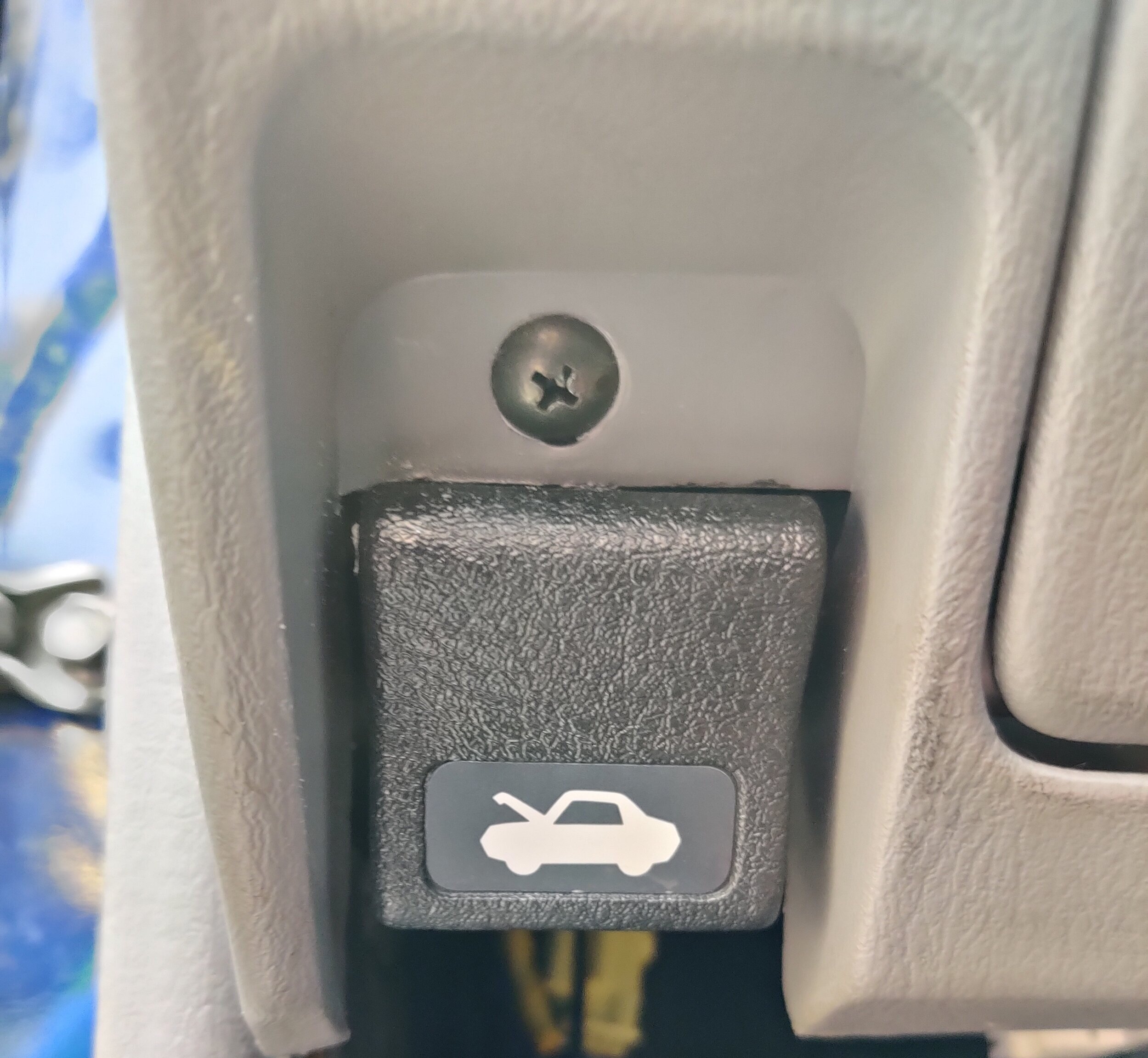
The last thing on the list of trim pieces is the lower portion of the dash under the steering wheel. There are two screws located on the lower section,with these removed you can pull the top clips of it out and slide this piece out of your way. This will allow you more access and room when running the wiring and vacuum hose.

This is the piece we are talking about. Down near the hood release your will find one screw, the other is located in the same lower area near the center console.

and this screw.
Remove this screw…

Now you can pull out on the panel and it should come out pretty easily.
Now that we have plenty of open room to work we can run the wiring for the Lamco boost gauge, I ran my down the left side of the wheel and used a zip tie to hold it close. Then around the back side of where the steering wheel shaft meets the bracing and on across to pop out in the stereo wiring area, plugging it into the open connection and finishing the wiring part of this install.

This is where it will live, so this is where i started.

Then run it along the backside away from anything that might move and damage it.
We will now move to the engine bay, looking behind the top mount intercooler you can find a circular rubber grommet to weather seal the engine bay from the interior. Removing this rubber cover you can now see a bit of the insulating foam that helps muffle the noise. You can push your finger through this to make sure the vacuum hose can make it’s way through to the gauge.

Here is our grommet. Remove that for now.

Now you will see the foam, make sure there is a pathway through it for the line to run.
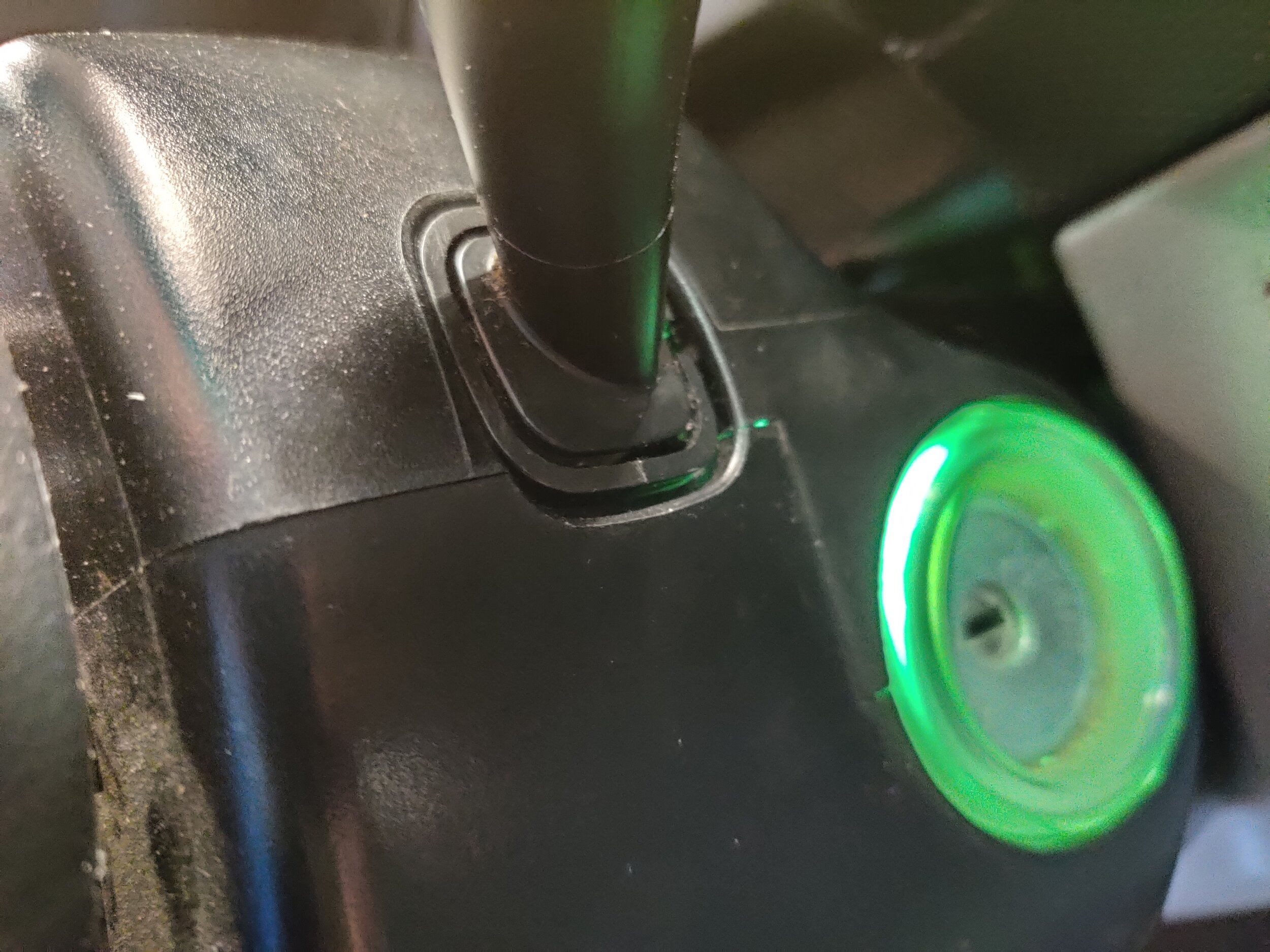
Now take a drill or knife and make a hole that allows the hose to travel through the fire wall while maintaining a seal to keep moisture and noise from entering the cabin. If you are having trouble locating the area where the hose will come through, you can use a flash light on the other side. A picture below will help you also identify the area to look for the hose poking through.

This needs a nice hole to run the vacuum line through and into the cabin.

The light at the end of the tunnel. Looking behind the center console on the driver’s side floor board, you can catch a glimpse of the light behind the Hvac box on the right. That is where you hose will be.
Start the hose by sliding it through the rubber seal, now you can pop it back into the hole in the firewall, move to the cabin to locate the vacuum line. Start pulling it through then you can find the wiring and follow the same path. You can also lightly zip tie the two together to keep track of them.

And now you can place it back in the firewall with the vacuum hose poking through.

Lead your hose up to where your wiring is. They can hang out there together for a minute. Testing that everything would fit.
Now is the time to make sure your vacuum hose was long enough, make sure your vacuum line is resting near the steering wheel and go check that it makes it to your target area for a vacuum source. I went ahead and used the factory location which is tees into the vacuum line that runs to the Bypass valve. Using a pair of wire cutters or knife you can find a a straight portion of the hose and cut into it. The attach your t-fitting to either side.

Everything tee’d in.

You can run the line under the side of the intercooler and tuck the hose back underneath to keep a clean appearance.
If you received the complete kit for the boost gauge kit you will have two pieces of metal that attach the rubber holder to the steering wheel plastic cover. You can use them as a template to mark and drill your holes for mounting it. I don’t have a template but hopefully the below photos and measurements will help you locate the best location.

Here are the mounting provisions for the gauge. Two pieces of metal with holes in them. Super fancy!

Threaded side goes on the inside to hold it tight to the steering column cover
You can install the rubber gauge holder onto the steering column cover before sliding it back on. I would recommend removing your left side multi function stalk to allow you to pivot the cover out of the way when reinstalling the gauge cluster and gauge surround. Only two small screws hold it in and you can slide the switch out and let it hang for a minute.

My gauge pod was installed on my STi cover and I just swapped it over.

Gauge cluster back in.


Having the multi function switch out makes putting in the cluster and surround that much easier.
Up next we will pop the gauge cluster back home, making sure to plug everything back in, then install the surround . Now you can pivot the column cover back in to position and attach the electrical connection and vacuum hose to the boost gauge. If you have wire covering from the kit or any shop you can use that to make it look a little bit nicer, instead of just having two wires and vacuum hose running up into gauge.

Getting ready to snuggle in with the pod and read some boost!

You can add a plastic wiring shroud for a classy look!
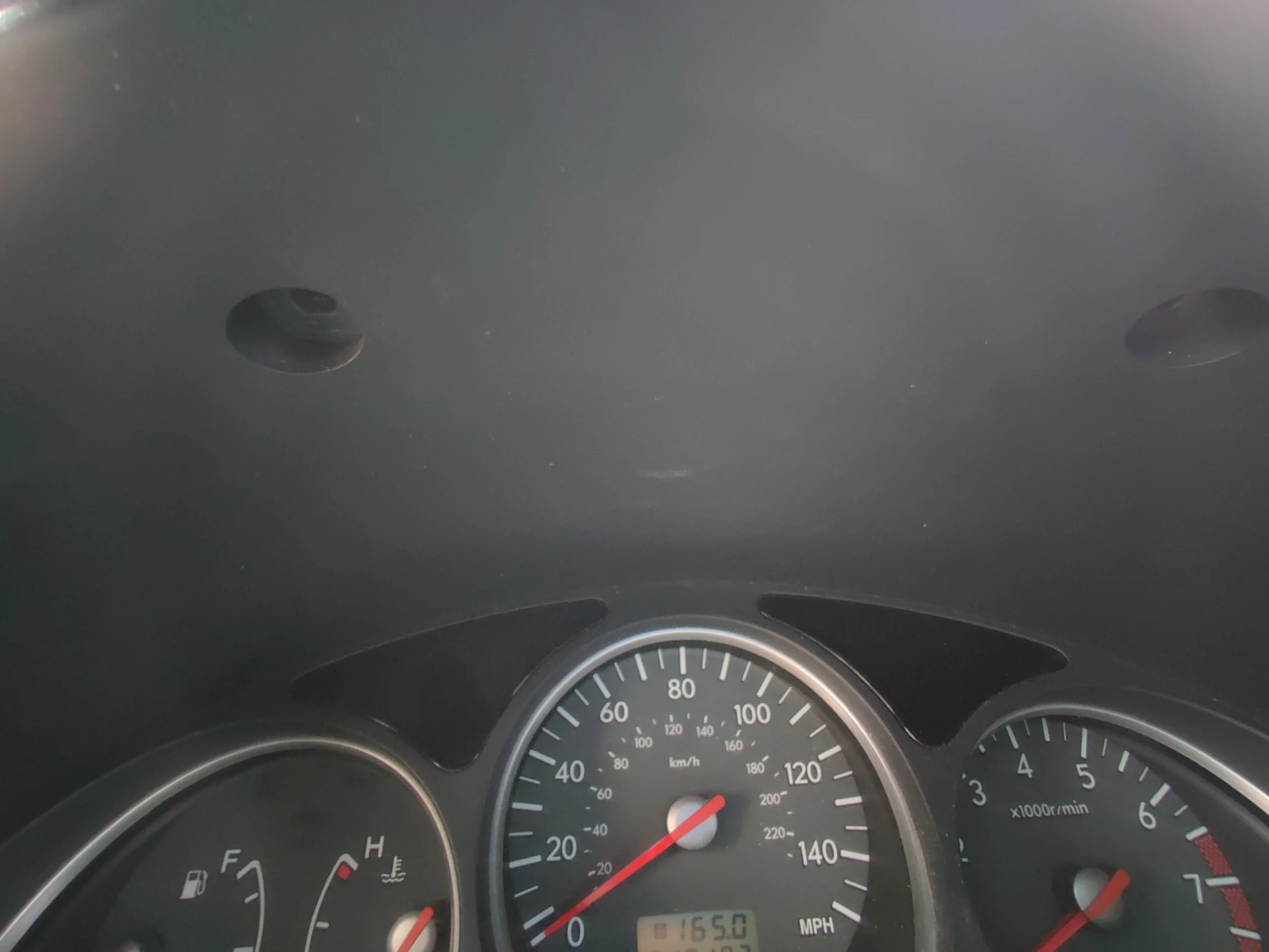
Before putting everything back together this is a excellent time to test that everything is still working. Start up your car and check for the boost gauge coming to life and moving and everything still running on your gauge cluster. If all is well you can go about putting everything back together in reverse!

Boost time!… Or vacuum time if you are at idle.
Congratulations! You have the ability to watch a gauge tell you that some air pressure is being built up! Even though most of the time you won’t be able to look upon it as you are too busy driving and enjoying the boost!