04-06 STi caster adding lower control arm install! Less weight, better handling, more caster... What more can you ask for!
Shortly after lifting my Forester and figuring out that I wasn’t able to fit my newer larger tires without a bit of body modification, i.e cutting/hammering. I thought, there might be a better way. Understanding that Subaru had parts in their own bin that could help with this, I tracked down a set of 04-06 STi arms.

Many visual differences to see but the unseen performance gains are what is really worthwhile!
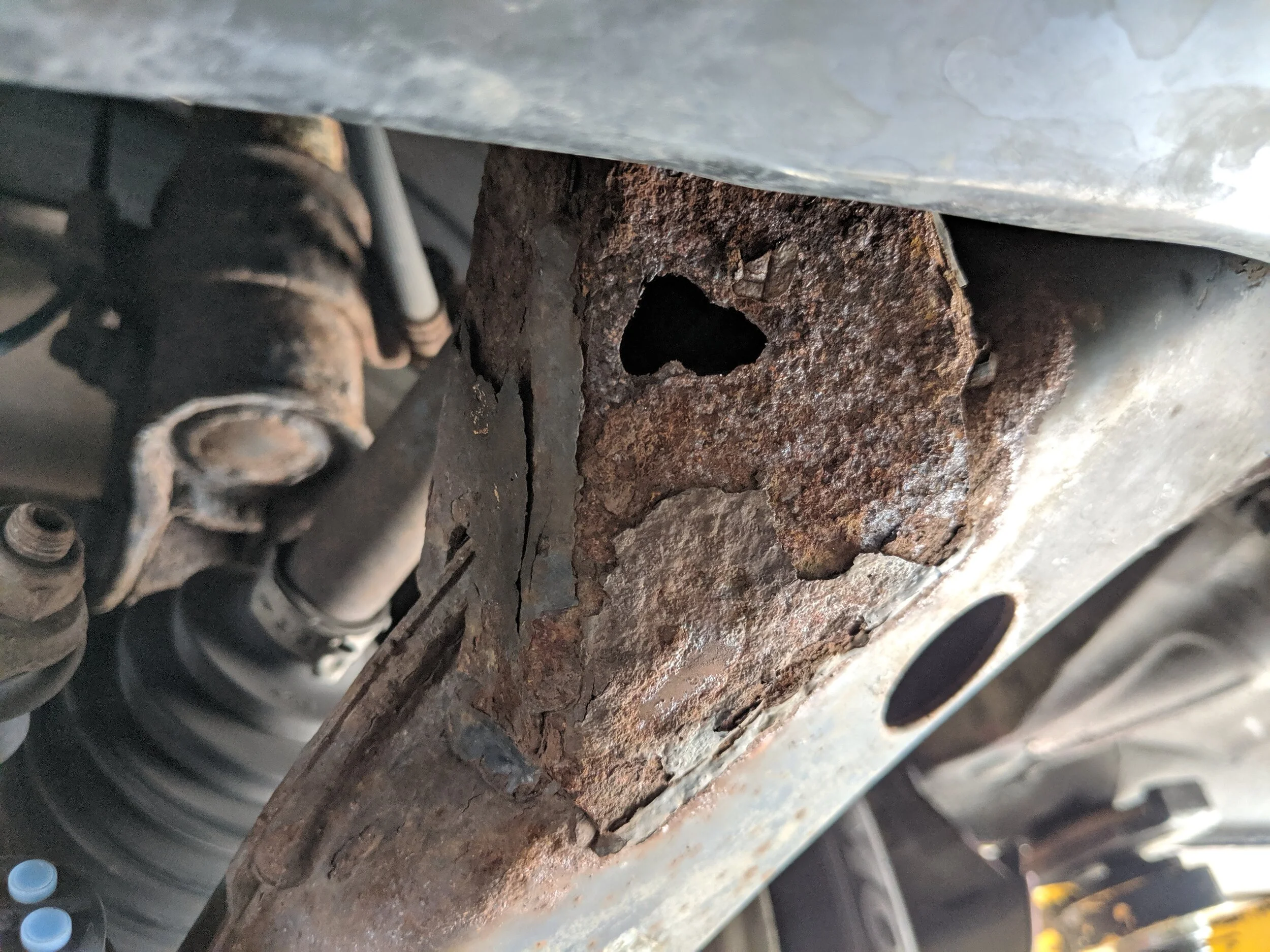
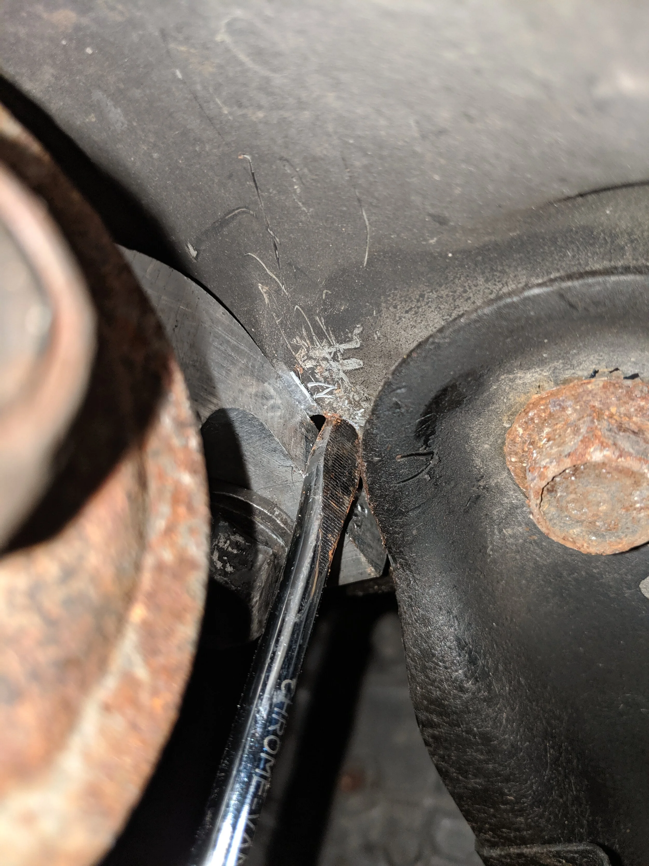
Another reason you may want to swap out your old control arms.. Rust is taking over…
Caster is the name of the game, that 04-06 STi lower control arms bring to the party and will help fit your larger tires/achieve better turn/handling. Caster is the angle of an imaginary line through the tires contact patch and following the strut up to the strut top. When you lower caster the wheel is pushed towards the rear of the front fender, adding caster pushes the wheel towards the front of the fender.

A quick photo to help with the idea of adding more caster.
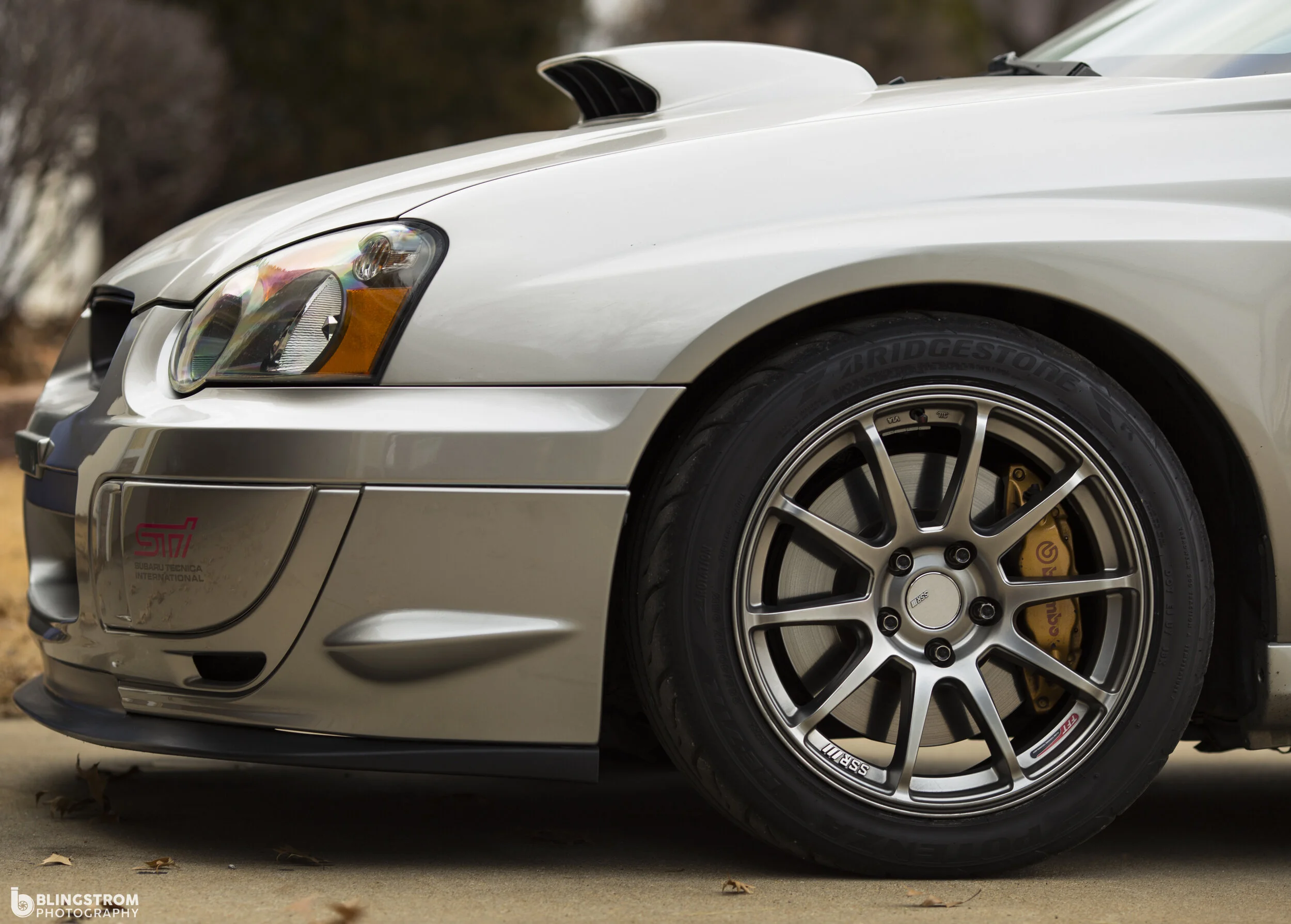
On my STi i use many caster adding products to help with turn in. When you look at the wheel it is no longer centered in the fender well but pushing towards the front bumper.
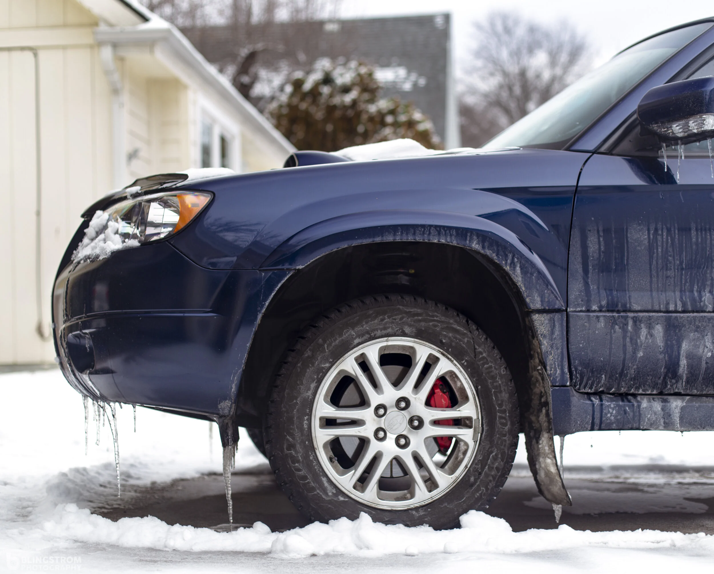
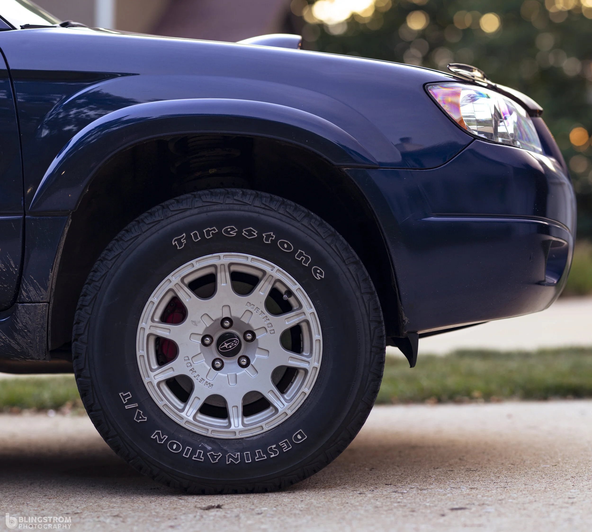
Here is the Forester before the caster mods. You can see how further back the wheel sits in the fender in comparison to the STi above it.
03-08 Forester’s are not blessed with much caster and that isn’t a big deal. But if you lift them you will find that your caster has slid even further down the scale, pushing the wheel towards the rear of the front fender and can cause tire rubbing with aggressive tire fitment. With 04-06 Sti arms we will fix this issue.
Time frame
This is a pretty labor intensive job and also passes through many bolts that have lived their whole life without being turned. Breaking off bolts is a moderate concern to this project, I would give yourself a good two to four hours for this job. It can go quite quick if everything comes apart easily, but beware of those rusty seized bolts/nuts/ball joints.
Tools
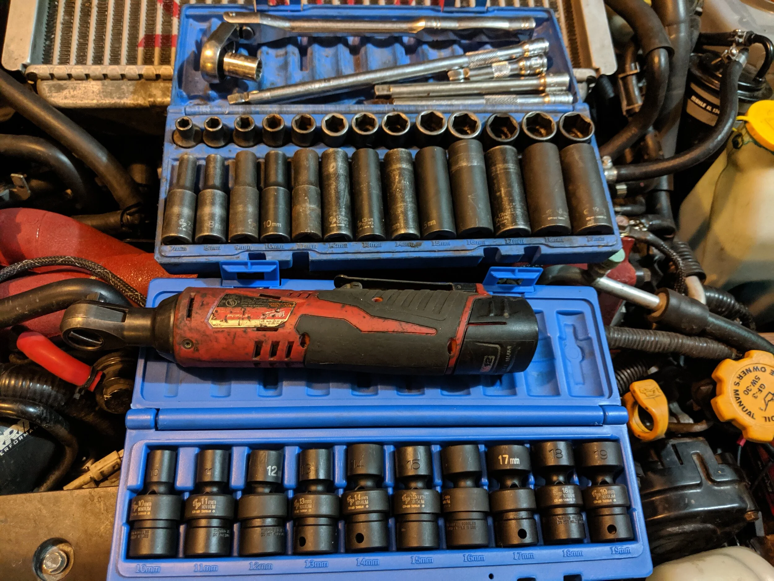
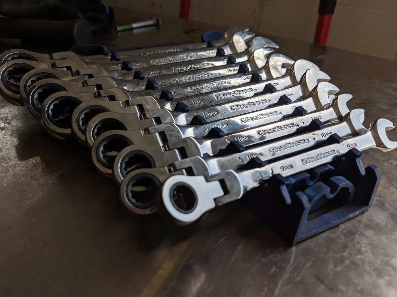
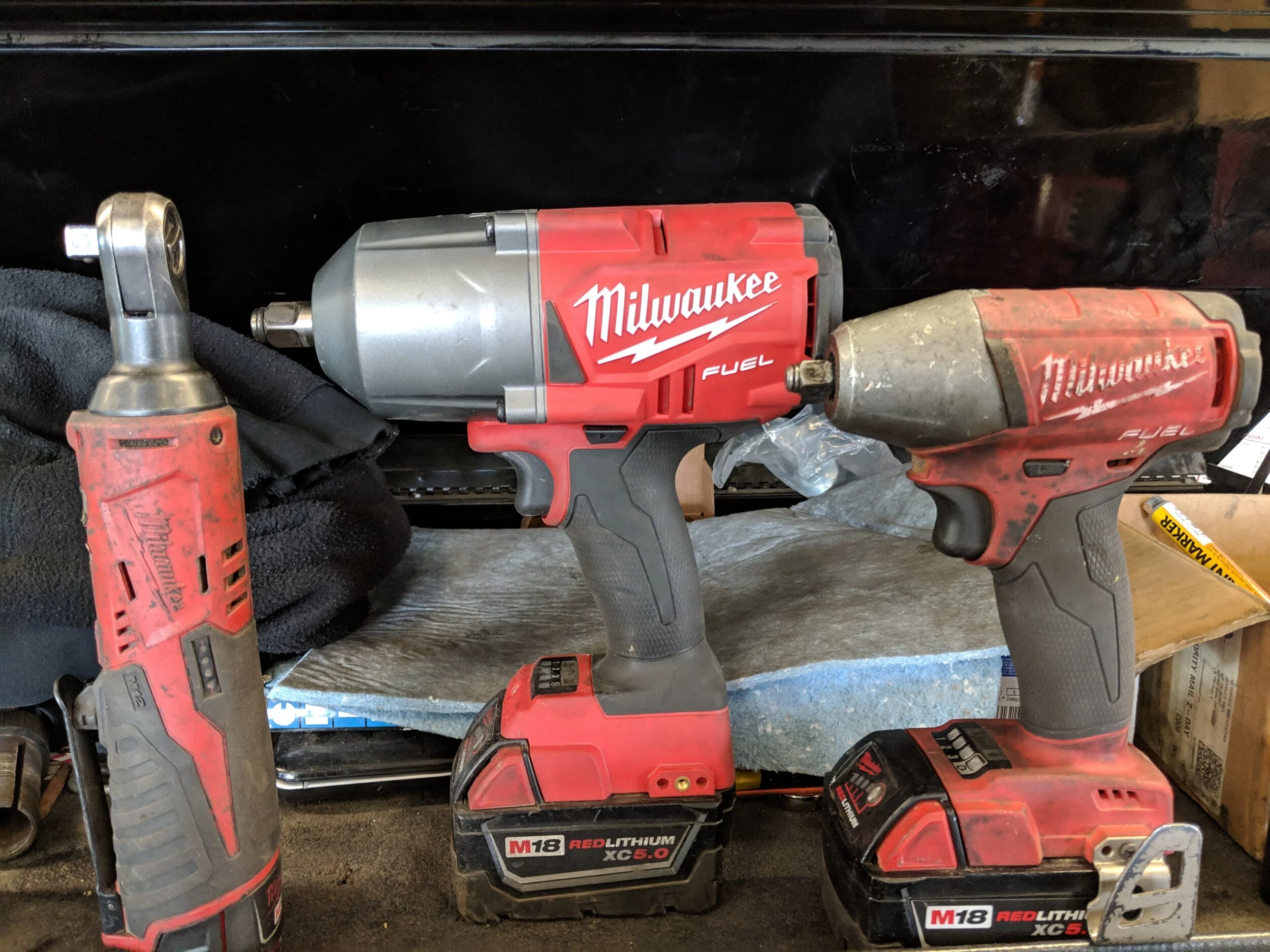
Your typical 3/8th and 1/2” socket set will be necessary. Your favorite ratchet, breaker bar, and air/electric tools to help rattle the stubborn bolts free. A couple of wrenches will round out your setup. Here are a few links to my favorites and most used.
Grey Pneumatic 3/8th socket set Grey pnuematic wobble socket set : These will start off the list. You will need your 12, 14, 17 and 19mm sockets will help get this job going.
Parts
Of course the parts listing includes 04-06 STi lower control arms. But if your lower control arm rear bushings (transverse bushings) are the original it is time to replace those. Part number for the STi arm is 20202FE800 for the right and 20202FE311 for the left.
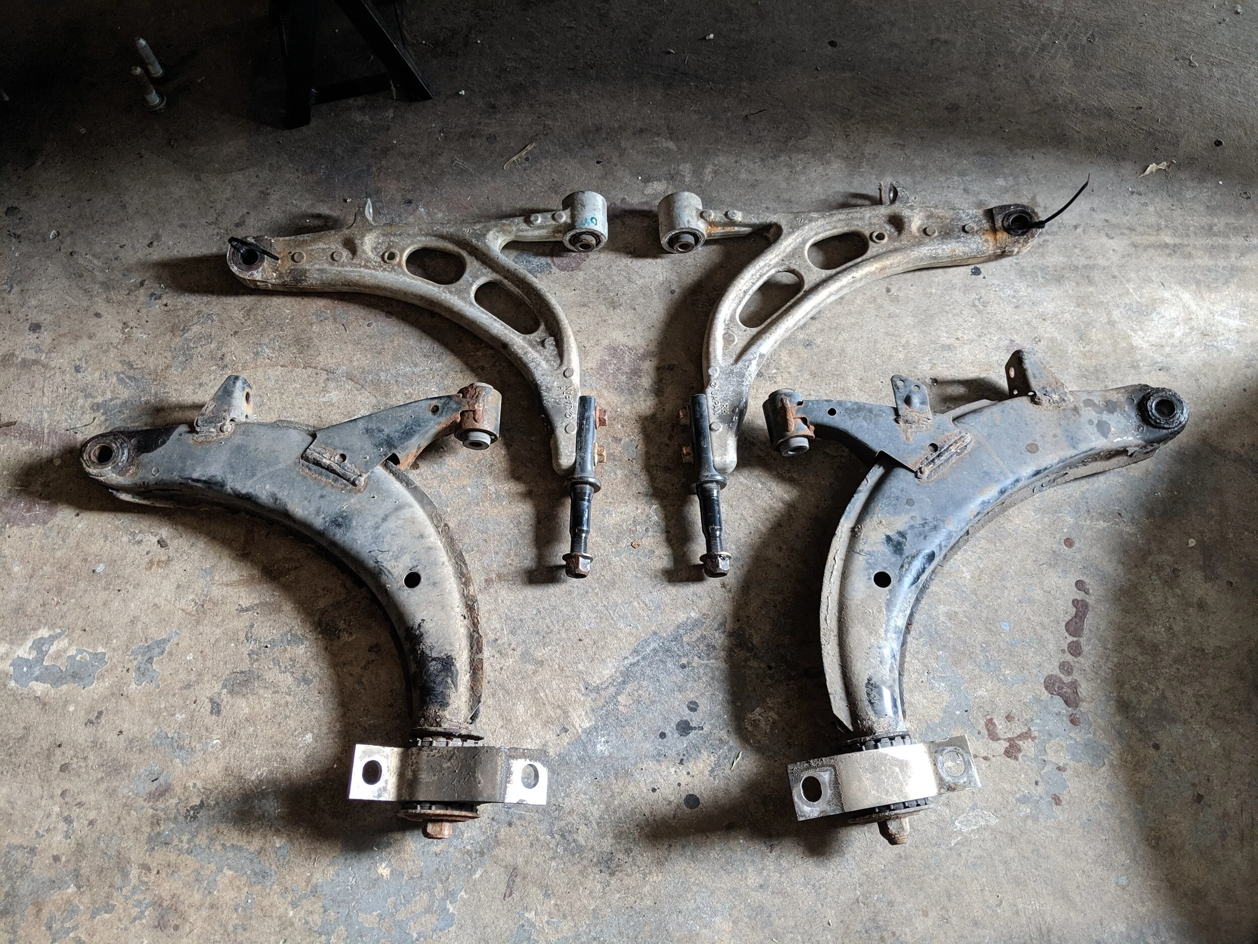
Sti aluminum arms add many benefits and even look quite a bit better!
The transverse bushing and mounts can be found new from Subaru. These are the 06-08 Forester version and the part numbers are 20201AC120 and 20201AC130. They are side specific so make sure you are getting the correct sides.

If you are replacing the control arms and these bushings are the original, it is a great time to upgrade these too!
Install
We will begin our install like any other suspension install. By lifting the vehicle and installing it on jack stands, then double checking our them before starting your work. With everything stable you can remove the front two wheels.

Up and away we go.

This is an excellent location to support your vehicle while giving you a good amount of height to make working underneath the car easier.
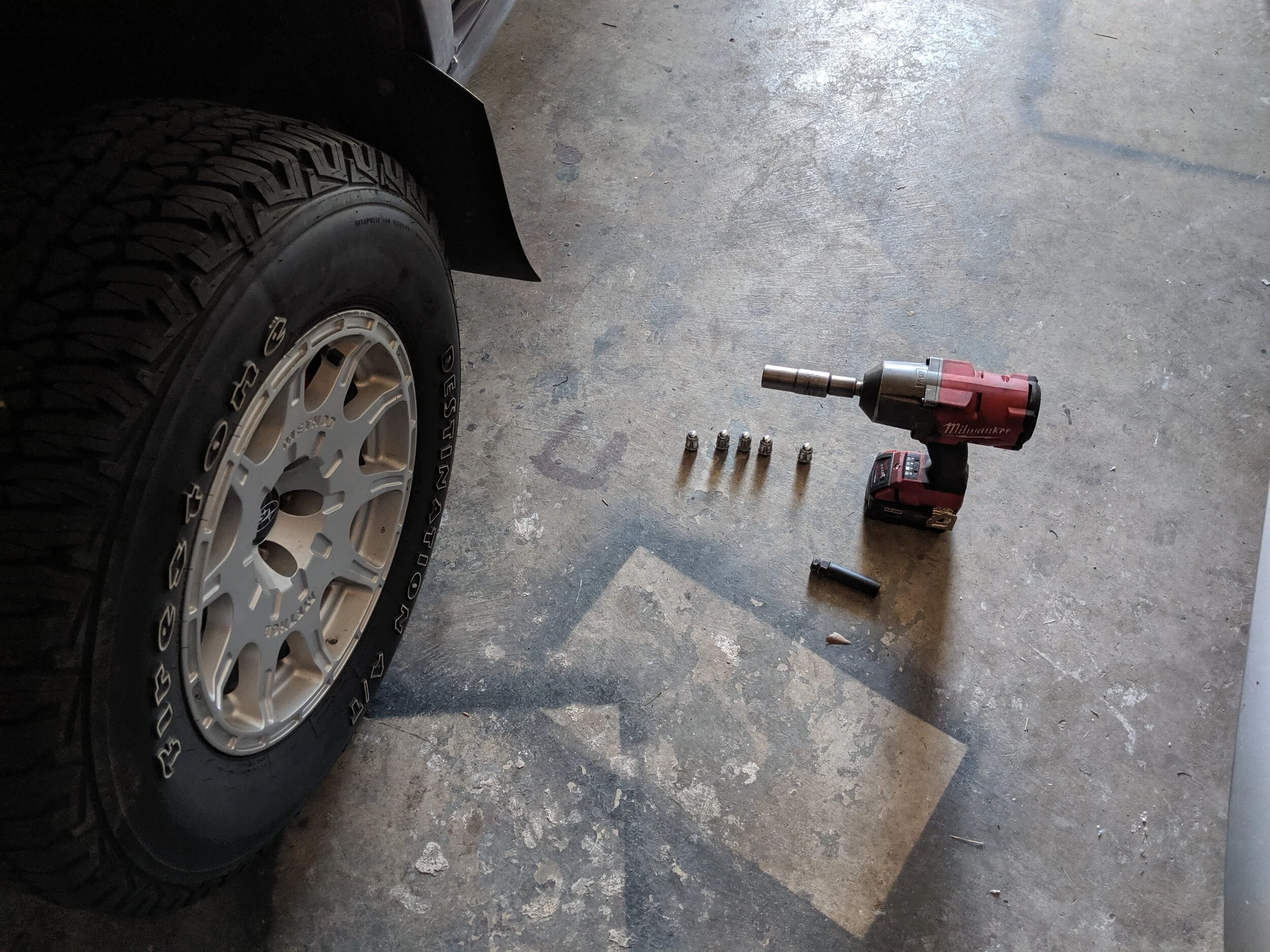
With your lugnuts off we can get to the suspension hiding behind the tire.
For your next step you can remove the axle nut with a 32 mm socket. This will insure that the axle won’t be pulled out of the socket when moving the spindle out from the lower control arm.

Off with the axle nuts. This is just a precaution when you are moving the spindle around. If you move it too far with the axle nut bolted on, you can accidentally pull the axle apart. Making your fun install a less fun time.
Next we can get underneath the arm and undo the cotter pin that holds the lower ball joint in place. With the 19mm nut removed we can break it free from the lower control arm now or wait for later. While you are in the area it is a great time to remove sway bar end links from the lower control arms.

Removing the cotter pin you can take your 19mm and spin the nut off. I then liberally add rust penetrant to help free the ball joint and arm from there years of rusting together.

At any time you can remove sway bar end link nut. I got it out of the way early.
Now because I was replacing both rear transverse bushings I went ahead and removed lower subframes from each. If you aren’t replacing the transverse bushings you don’t need to complete this step and skip past this. There are around seven bolts keeping each subframe in place, they are often very rusty given their low location on the vehicle. With the last bolt or two in you may want to situate yourself out from under or bracing the large subframe, because once the bolts are out it will be dropping in a hurry.
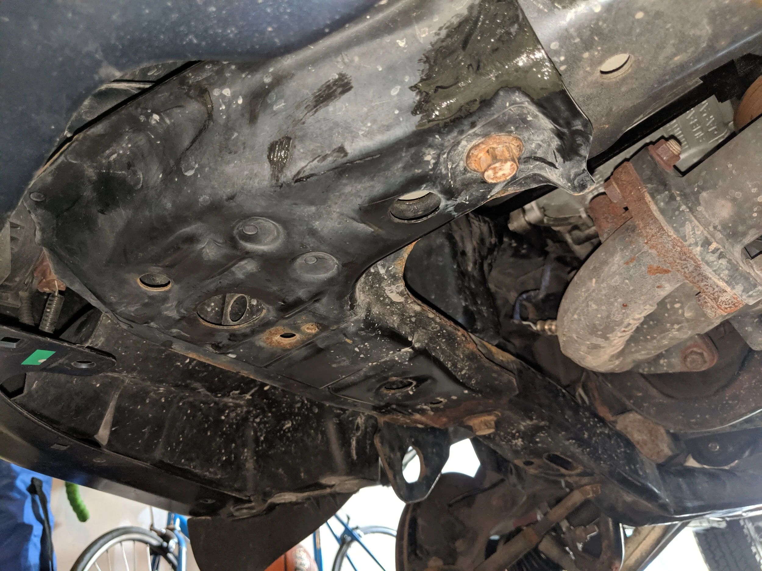
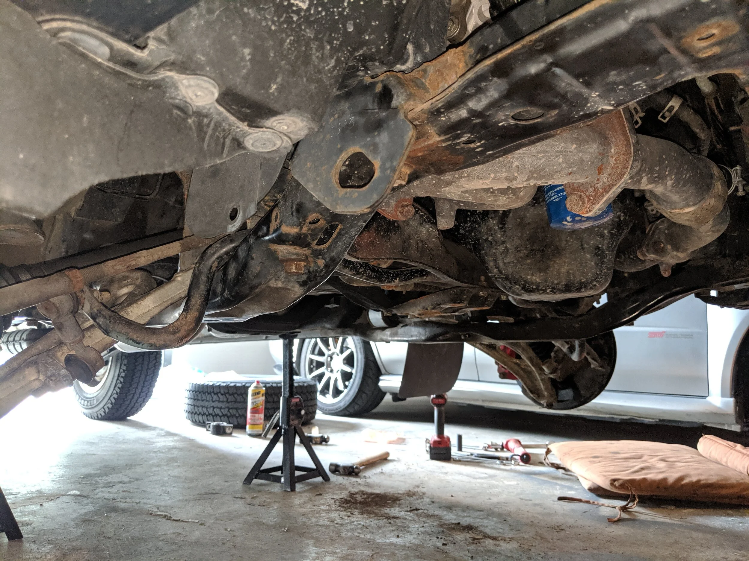
This is your lower subframe just to the left of the exhaust manifold. It stretches from the radiator support to just behind the transverse mount. It is held in place by seven bolts.

If you aren’t removing the subframe there is one of the holes to allow you to loosen the transverse mount and remove the arm. Otherwise you can remove the bolt in the center and far right to complete the removal of the subframe.

On the 06-08 Forester the subframes for the driver and passenger side are separate units. Here they are both uninstalled.
If you choose to remove the lower subframe you will now have plenty of space for replacing both the lower control arm and transverse bushing.You can leave the rear nut on the transverse mount because you will be removing them together and can take them apart outside of the car.
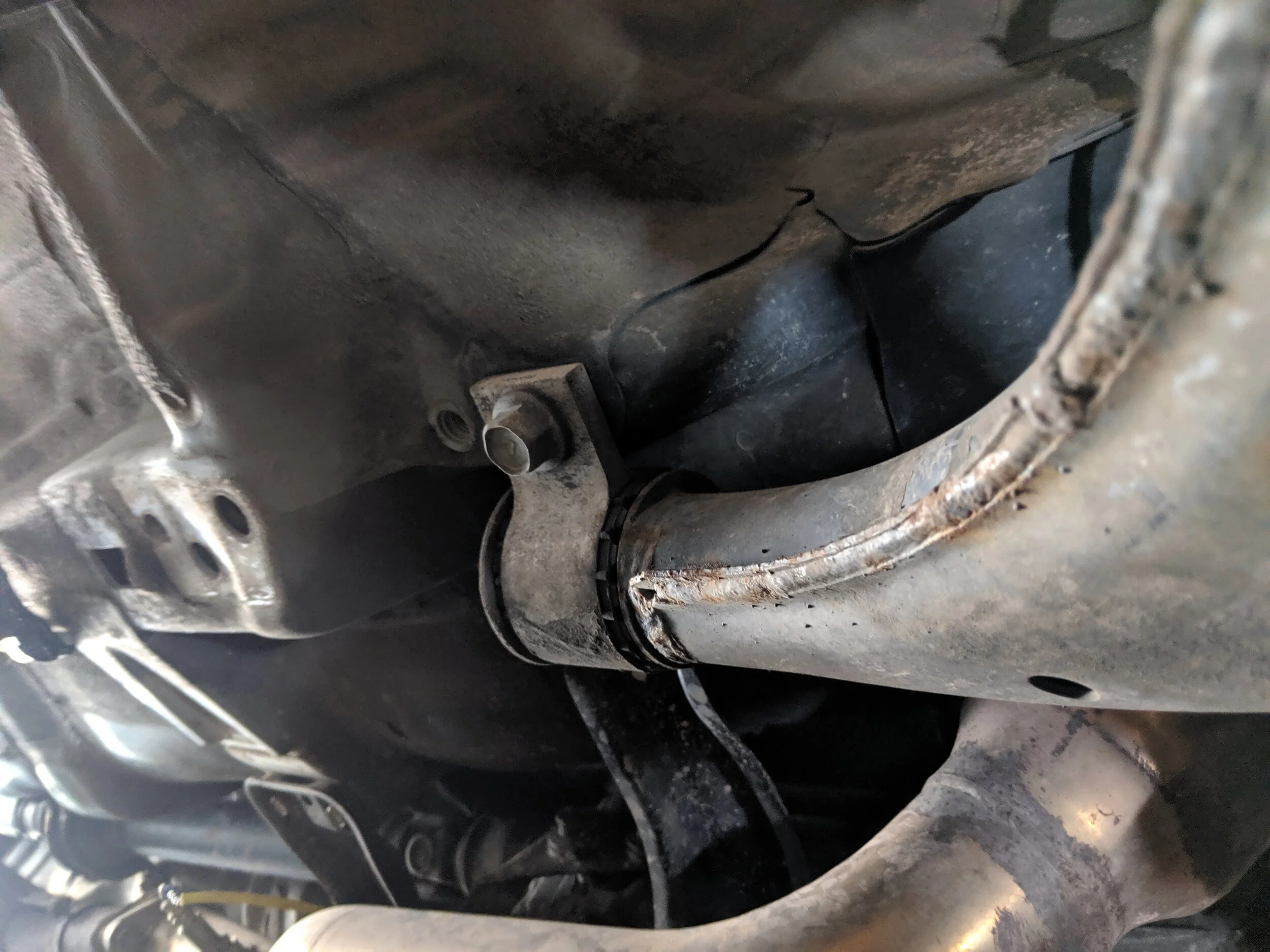
Here is the view of the transverse mount without the subframe in the way.
If you choose to leave the subframe in place and are leaving your tranverse bushings in place, now is the time to break the rear 22mm nut free. I often utilize a swift kick to get this nut loose as it is quite tight. You will also want to break the two 19mm bolts that hold the transverse to the body loose. This is necessary to help maneuver the lower control out with the lower subframe still in place.
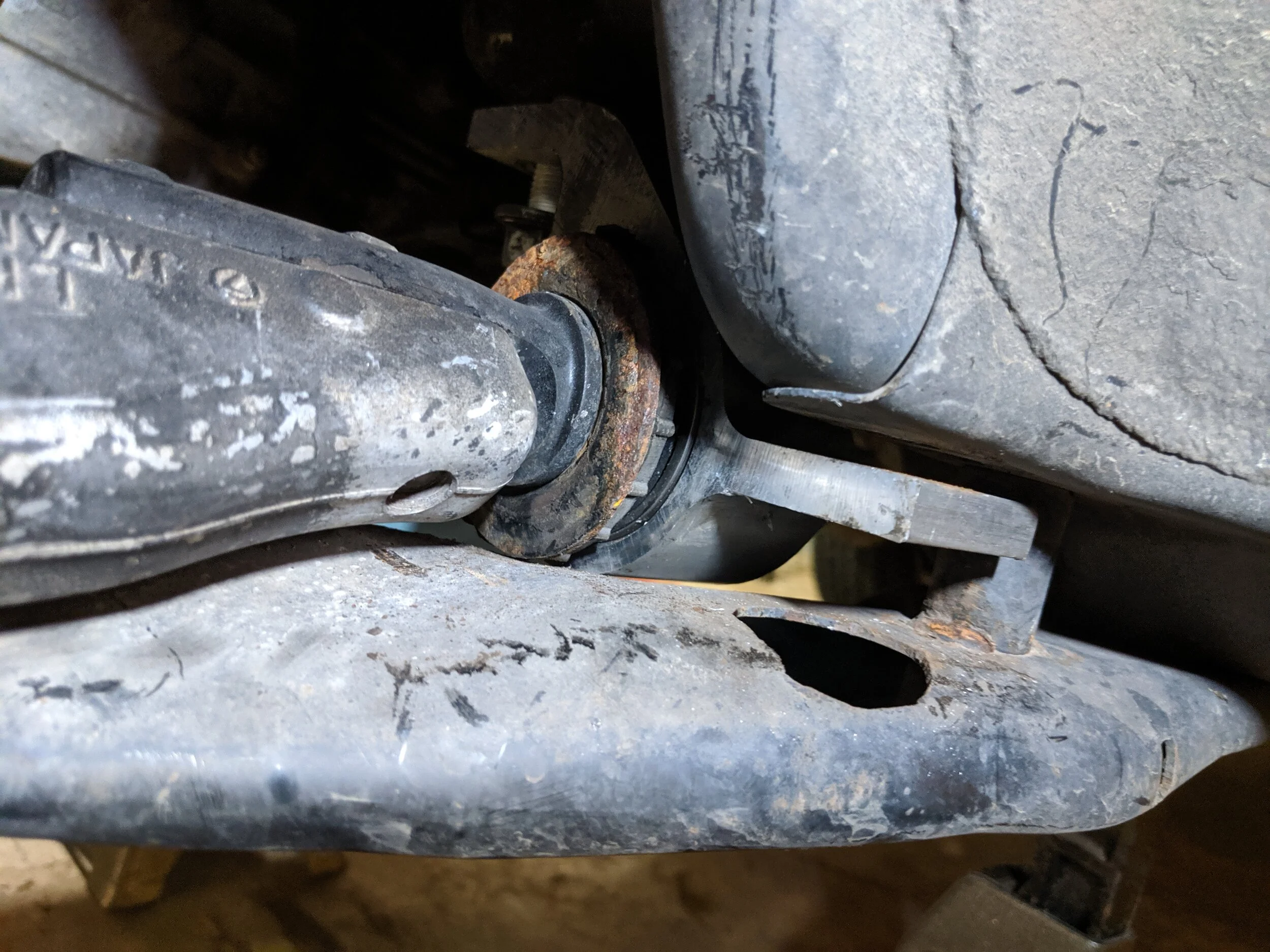
If you leave the subframe on this is what you will need to do. One bolt removed and one very loose to allow the mount to be shifted and allow for the arm to come out.

The nut is much more accessible with subframe off but you still will most likely need to use a wrench to loosen/remove it.
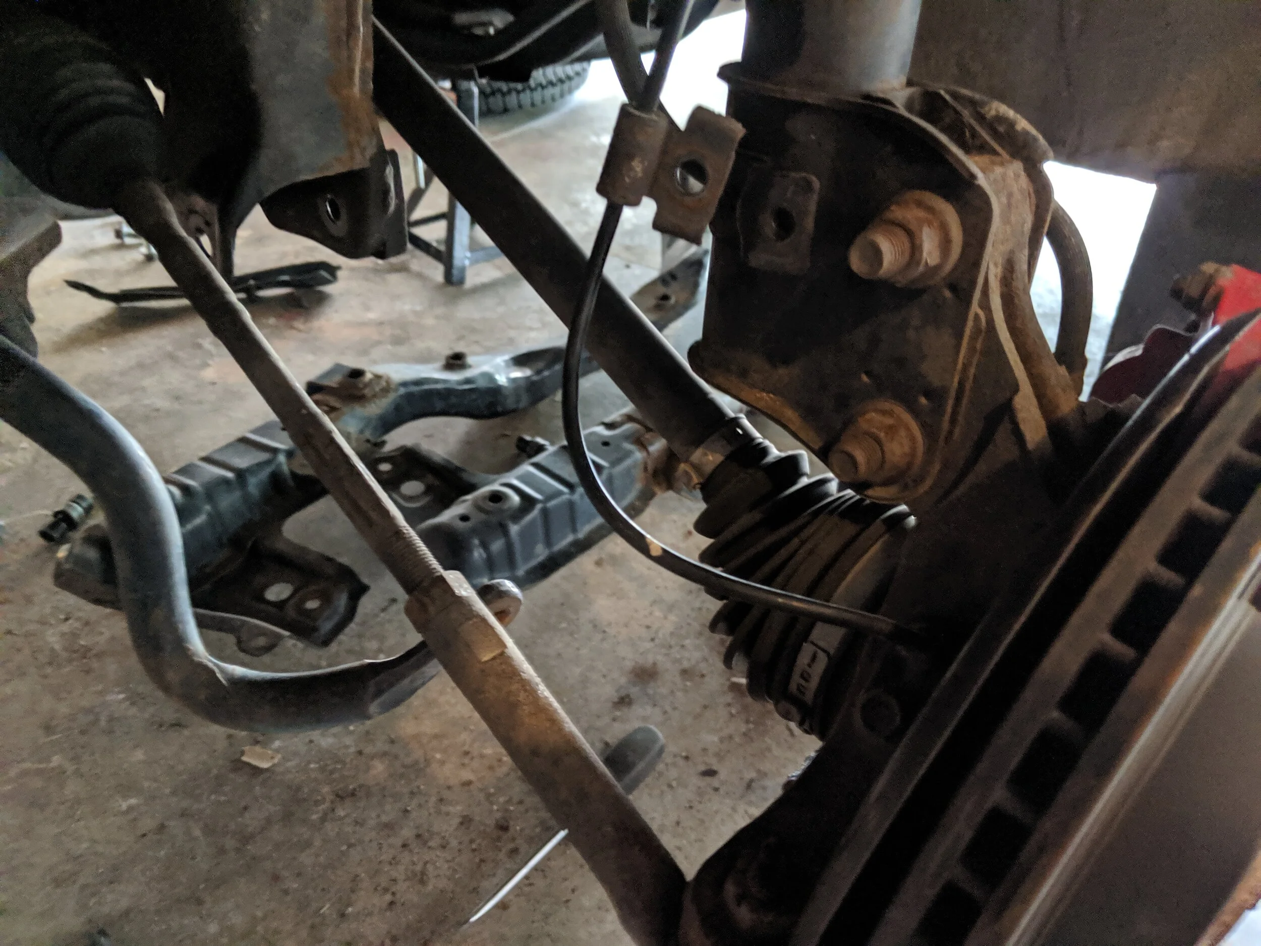
Now we will come to where are two paths converge again. With the transverse mount dealt with you can move to the front bushing, it bolts through near the steering rack. It will be a long 17mm bolt, hold the nut side with your wrench and get the bolt spinning to remove it. With this out of the way you can now pry it out and be one step closer to removing it.
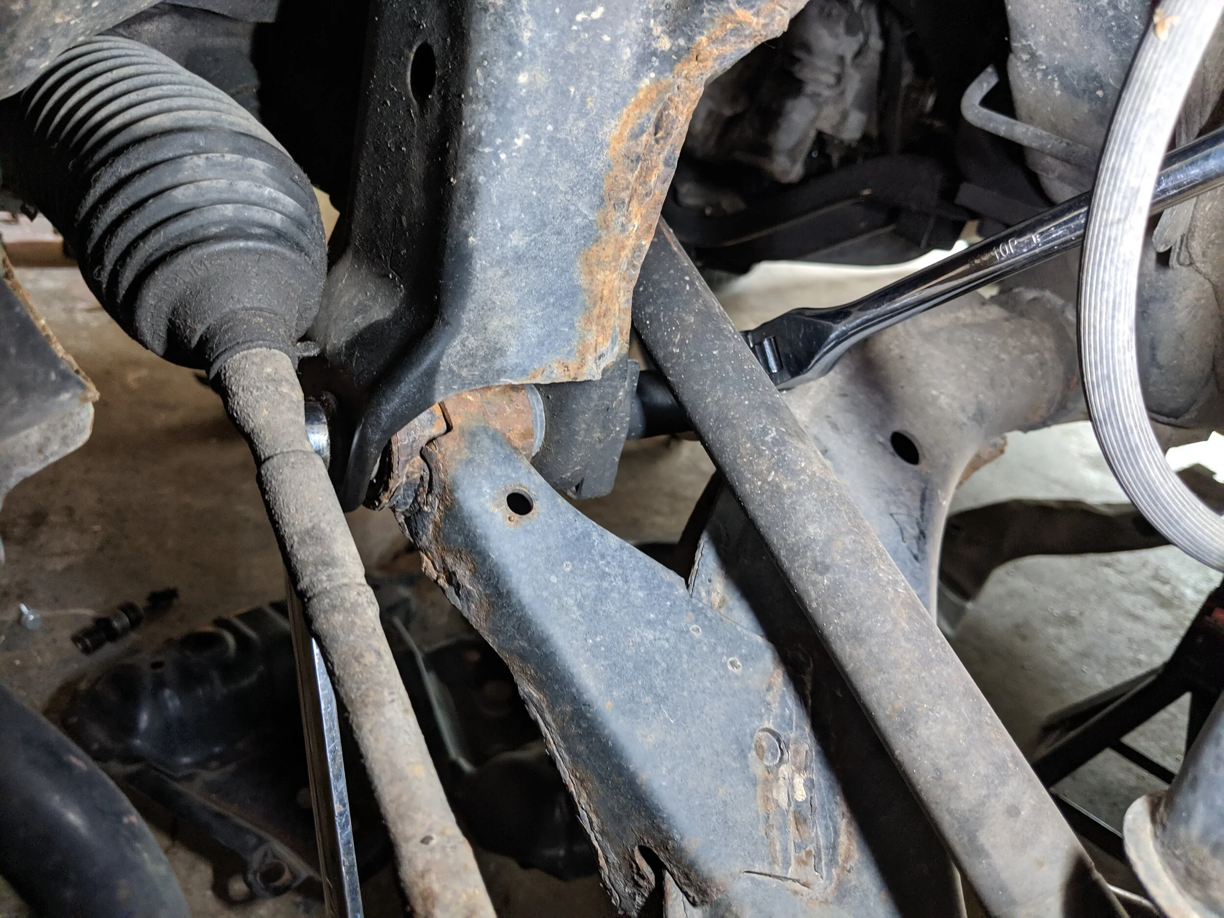
The front control mount is in quite tight quarters. It takes some maneuvering to get your tools on the nut and bolt, then a good amount of strength to break it free.
With the control arm loose of the inner two mount points you can either free it from the ball joint by giving it a few strikes from your favorite hammer. If you had broke the ball joint free earlier you are ready to free it and install the new unit.

With the bolt removed we can now pop the bushing down and the arm is mostly free!
With the arm removed and subframe there is lots of open space to play in.
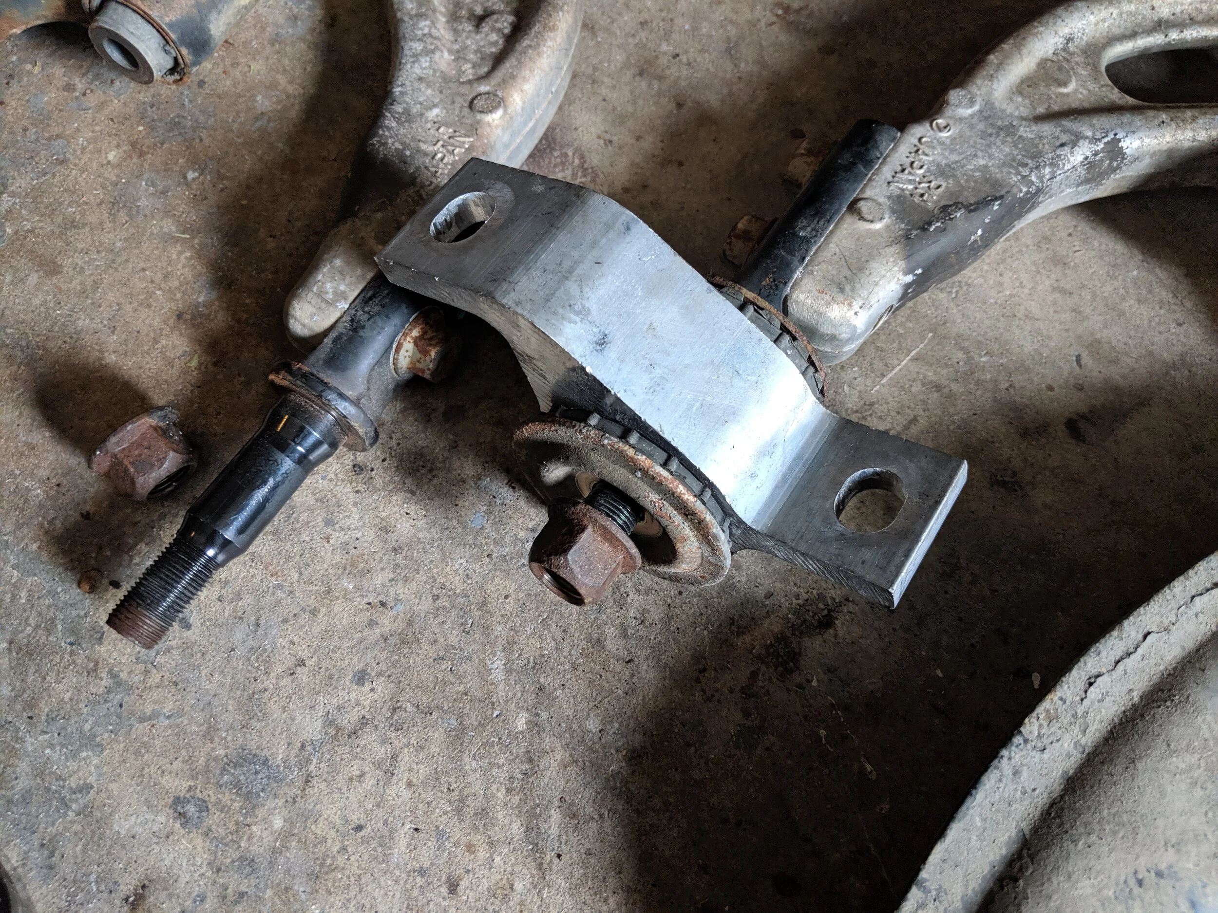
You will need to make sure your STi control arms have their rear steel mounting arms for the transverse are installed in the same fashion. If the steel part is flipped on one side it will add further caster on that side (around.5 additional caster) and may caster a caster imbalance. You will also need to have the steel adapters that allow the ball joint to be installed on the STi arm properly.
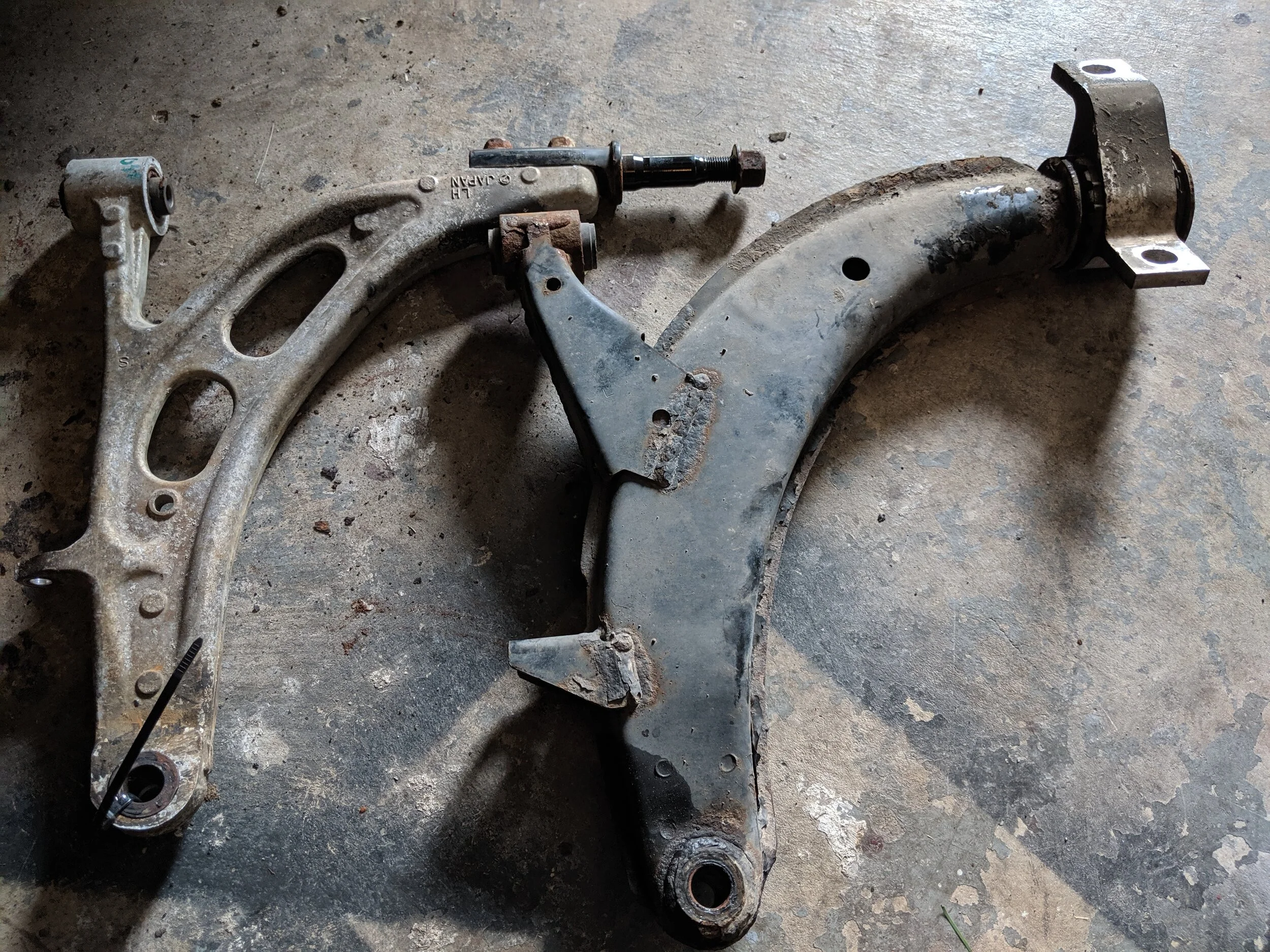
Here we go with aluminum Sti unit vs the standard Forester steel unit.

This is the standard pin installation. If you are looking to really max out your caster, remove the two bolts and flip the steel rod 180 and reinstall it.
If you left the subframe in you will need to install the control arm in the transverse mount first. With the control arm in the transverse mount you will shift it into place within the front bushing mount. You can now slide the bolt through the bushing to hold the arm in place. Lastly you will lift up the spindle and ball joint to install it into the control arm.
If you pulled everything out this is the time to install the new transverse bushings. You will need to reuse the the Forester bushing isolators and the STi inner washer. The washer is built into the Forester arm but the Sti arm is a different story.

With the subframe out of the way, this is a very easy straightforward install.
You can now reinstall the end links, making sure to run them completely down in order to keep them from knocking and making terrible clunking noises.
Going back together!
With all you bolts, ball joints and arms in their new homes you will take all the nuts and run them down. Having tightened all the bolts, nuts and cotter pins you can situate your transverse mounts. Pushing it forward on the chassis will increase caster and pushing towards the rear will decrease caster.

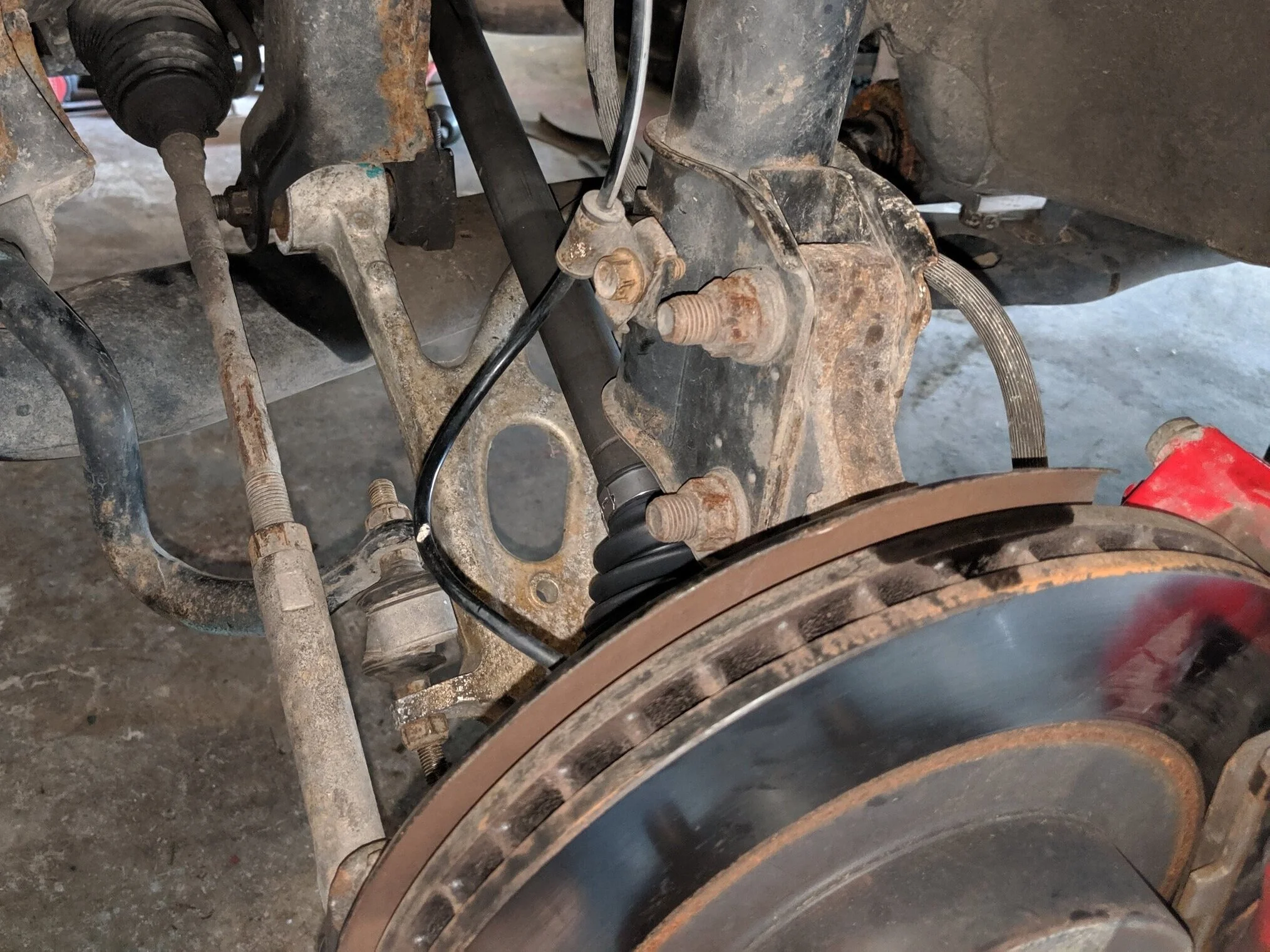
Here is the outside shot of the holes you can use to adjust caster.
This is one technique for helping you move that bushing forward to add a bit more caster.
You are just left with the subframe if you removed it, placing the bolts back in their homes and running them down will finish that off. Lastly you will need to install your wheels, lower the car off the jack stands and torque those wheels down.
Subframes back on and arms in their spots. We are ready to lower this car back down.
With all this done I would recommend a test steering back and forth to make sure everything is in it’s correct placement and not rubbing on to any components that may cause issues while driving. This would be a good time to take your car for a short test drive and listen for any abnormal sounds or steering issues.

Checking wheel to fender clearence.
Here is the after install photo. With around 4 degrees of caster the wheel is pushed toward the fender which keeps it from rubbing on turns!
As with any suspension change or install, you should have your alignment checked at the least. But for a modification like this you will need an alignment. For my vehicle I saw toe move out on both sides. This is also an excellent time that you can have your caster shifted to suite your setup.
Congratulations on the install! You can now enjoy better steering, a slightly wider track width and less rubbing if you had installed larger diameter tires. You also subtracted a smidge of weight from your control arms and strengthened them up! They are also a bit easier on the eyes when underneath the car!
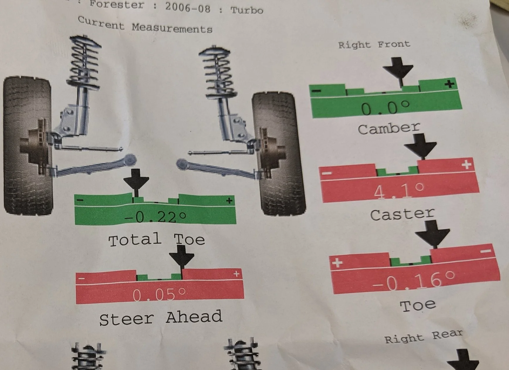
Toe angle on the right front was out. This will cause more tire wear as your tires aren’t pointed straight ahead.
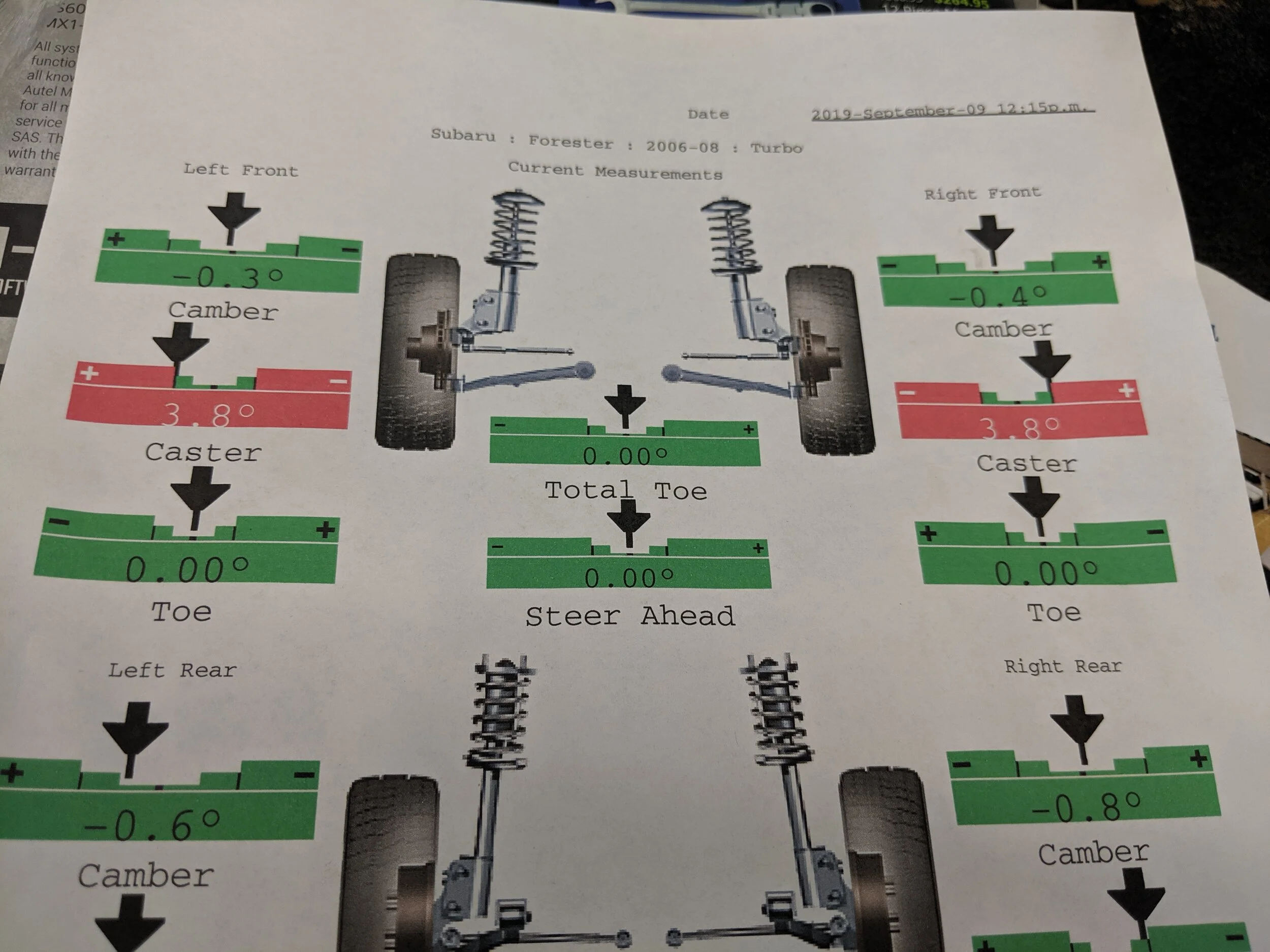
Here is the final numbers. Steering wheel straight ahead and toe right on.
Amazon tool links
Grey Pneumatic 3/8th socket set
Grey pnuematic wobble socket set :
Milwaukee 3/8ths electric ratchet
Milwaukee 1/2” electric impact
Gearwrench ratcheting wrenches.
Mayhew Pry bar set
Subaru part numbers!
06-08 Forester transverse bushings 20201AC120 and 20201AC130
04-06 STi aluminum lower control arms
20202FE800 for the right and 20202FE311 for the left.