Vf48 turbo rebuild... We can rebuild it! We have the technology!
There comes a time in every turbo owners life which is to replace a failing turbo. With there being a plethora of choices today from buying a used turbo, rebuilt turbo, eBay special turbo, upgrading to a larger unit, send it off to a shop, or the Diy CHRA replacement. Today we will go ahead with the do it yourself CHRA replacement, which is generally a mid range among pricing and has a quick turnaround time.

This CHRA comes from Melett which is headquartered in England.
Among the turbo rebuild kits you can choose a new CHRA (center housing rotating assembly) or a inner seal kit for your current center section. I prefer a new CHRA for it’s post assembly testing and professional balancing. A turbo can spin up to 250,000 rpms and a little wobble can make a big problem at even half these speeds. Without proper balancing these parts can easily fail right after you have reinstalled it.. with this in mind I have stayed with full CHRA replacements.

CHRA in all of it’s glory. ready to be installed.
Tools necessary for this repair would be an 8mm 10mm and 17 mm sockets or wrenches. A deadblow or rubber hammer, a razor blade and a small screwdriver or pliers. Replacement parts will be the CHRA of course, High temp red/orange RTV sealant, a new oil return line gasket and crush washers for the coolant lines and oil feed unit.
Optional replacement parts would be a new oil drain tube with time and heat it becomes quite brittle and hard. Turbo coolant return hose as it befalls the same issues of heat and can become soft over time. Both the turbo to uppipe and downpipe gaskets should be changed out to keep your exhaust in the turbo for maxmum spool.

C shaped coolant hose. New and old. Subaru coolant hose
Your first challenge will be removing the turbo from it spaghetti mess of hoses and wires and releasing it from the exhaust stream. With it out of the vehicle you can now start the dissection. With the first step being removal of the hard coolant lines that are bolted on. Now you will want to mark the coldside housing to make sure to clock the turbo properly when rebuilding in reinstalling. If you are off it will make many more headaches down the road as the intercooler won’t line up properly.

Turbo hiding out in the engine bay. Heat shield and various lines removed. Iag braided oil line

Two coolant banjo bolts to remove.

Hardlines off and set to the side for later.
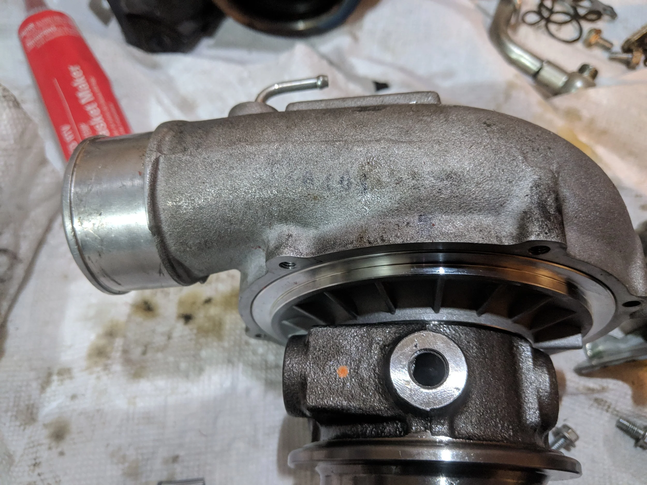
Hard to see in the image but there is a light mark straight up from the oil feed hole. Making your rebuild that much easier.
Next we will remove the two 10 mm bolts that hold the oil drain on. With these removed the turbo is free of its external fluid hardlines.

Oil return line ready for removal.
There is a small circlip that helps hold the wastegate arm to the flapper door. Using a small screwdriver or pair of pliers you can easily pop it off freeing the arm.
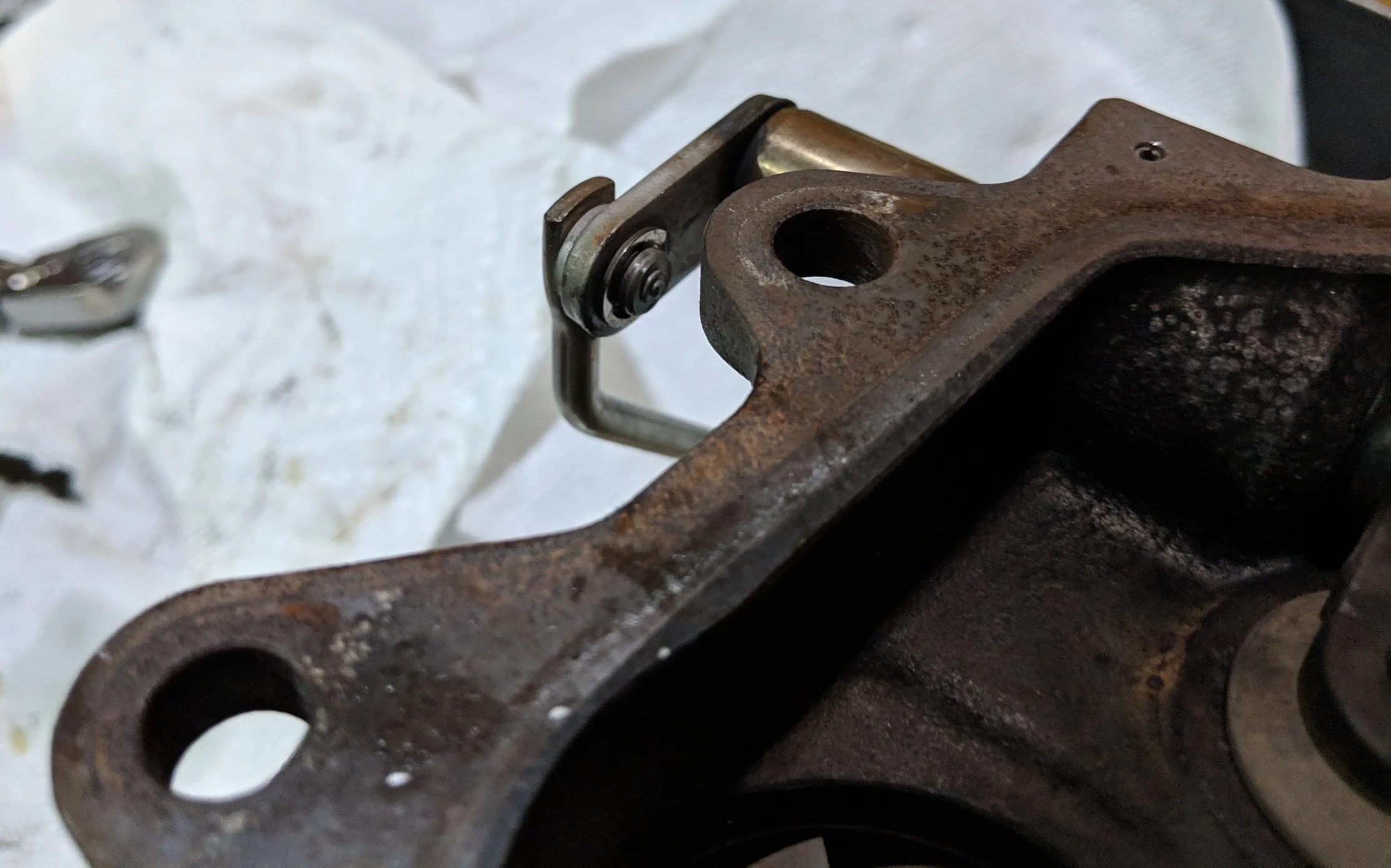
Circlip shown above comes off easily with a pocket screwdriver.
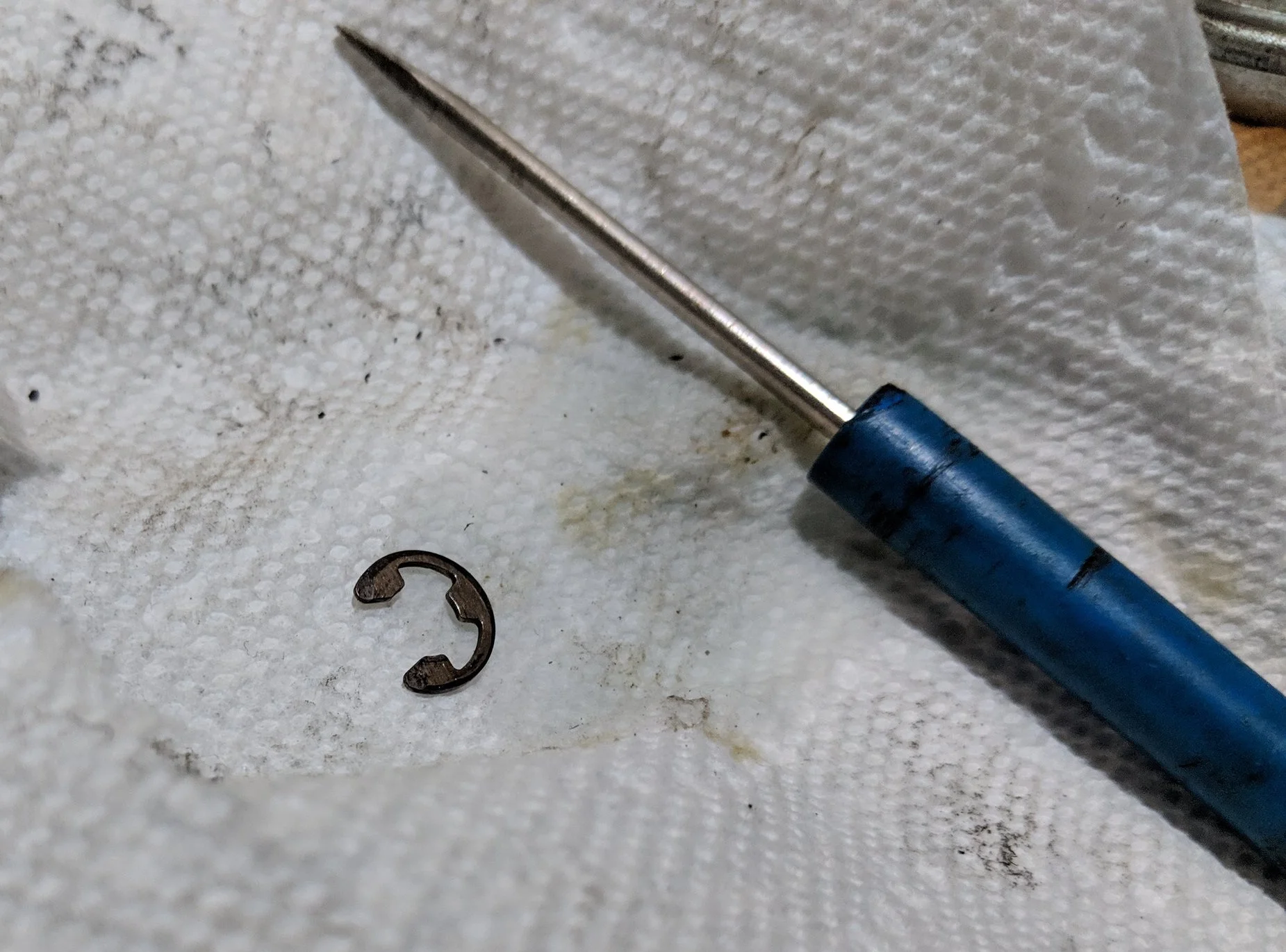
Circlip removed and set aside.
Removing those we can now the hotside housing which is clamped on with a bolt and 10 mm nut. After slipping the clamp off you will release the CHRA from the hot side. If you have an older rusty unit it may take a few dead blow hits or a chisel bit to help free them from one another.

The clamp and nut is all that is left to hold on the hotside to the center section.

Hot side clamp being undone. Easily removed by hand.

Removing the clamp allows the hotside to slide right off.
On to the cold side reside six bolts that attach the cold side housing and CHRA together. Two which bolt the wastegate actuator to the cold side unbolting these will undo the actuator and ready you to split the CHRA from the coldside housing.

The six bolts that hold the cold side to the center section. Note the two wastegate bolts are different.
Now having removed the six bolts you will take your dead blow hammer and begin to tap around the outside of the coldside. A layer of RTV resides within to keep the air from leaking out and it needs some convincing to release the two. Make sure to tap around the outside in a circle with even strikes. When it starts to release keeping the pattern going. if you twist the coldhousing too far on the CHRA it will cut or rough up the inlet housing.
Unbolted and ready for a bit of persuasion with a mallet.

After a couple rounds of deadblow hammer strikes it will start to come apart. Make sure to keep it even to not rough up your coldside.
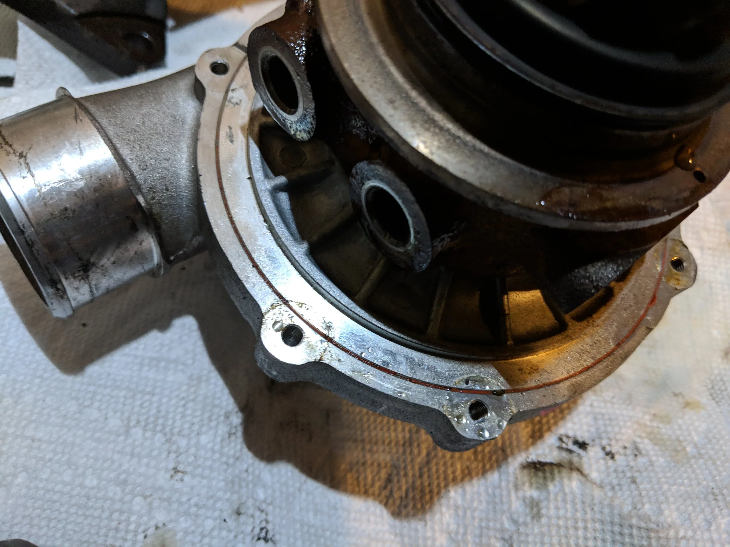
Once the housing is fully released can start cleaning the old RTV off. With a razor blade or small screwdriver to help remove it. Using very soft pressure you will easily remove the RTV., you will even find your fingernail can take it off with ease. With too much pressure you can mar up the surface of the housing and we don’t want to leave any openings for air to leak out of. The RTV should take care of any small imperfections in the surface but take care during this step.
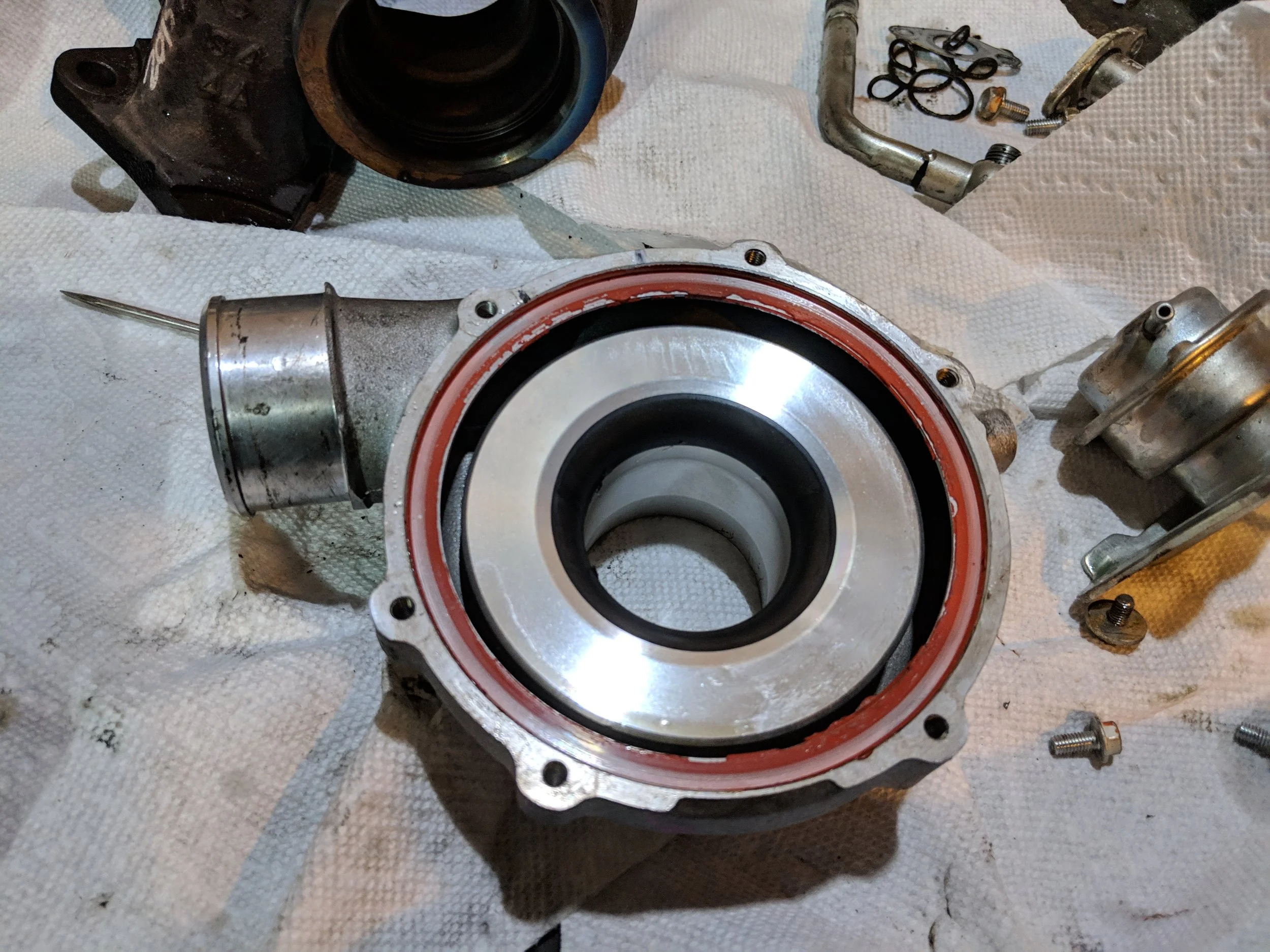
Peeling it up with a razor blade, pocket screwdriver(use no pressure) and even your fingernail.

Coldside cleaned and ready for RTV.
With your thorough cleaning you can now take a lint free cloth and brake clean to prep the surface for the new RTV. Next we will run a Rtv bead around the entire coldside/CHRA mounting area. I try for a bead that is a little less than half of the width of the mounting area. Too much Rtv can cause it to ooze out into the cold side housing for your engine to later ingest.
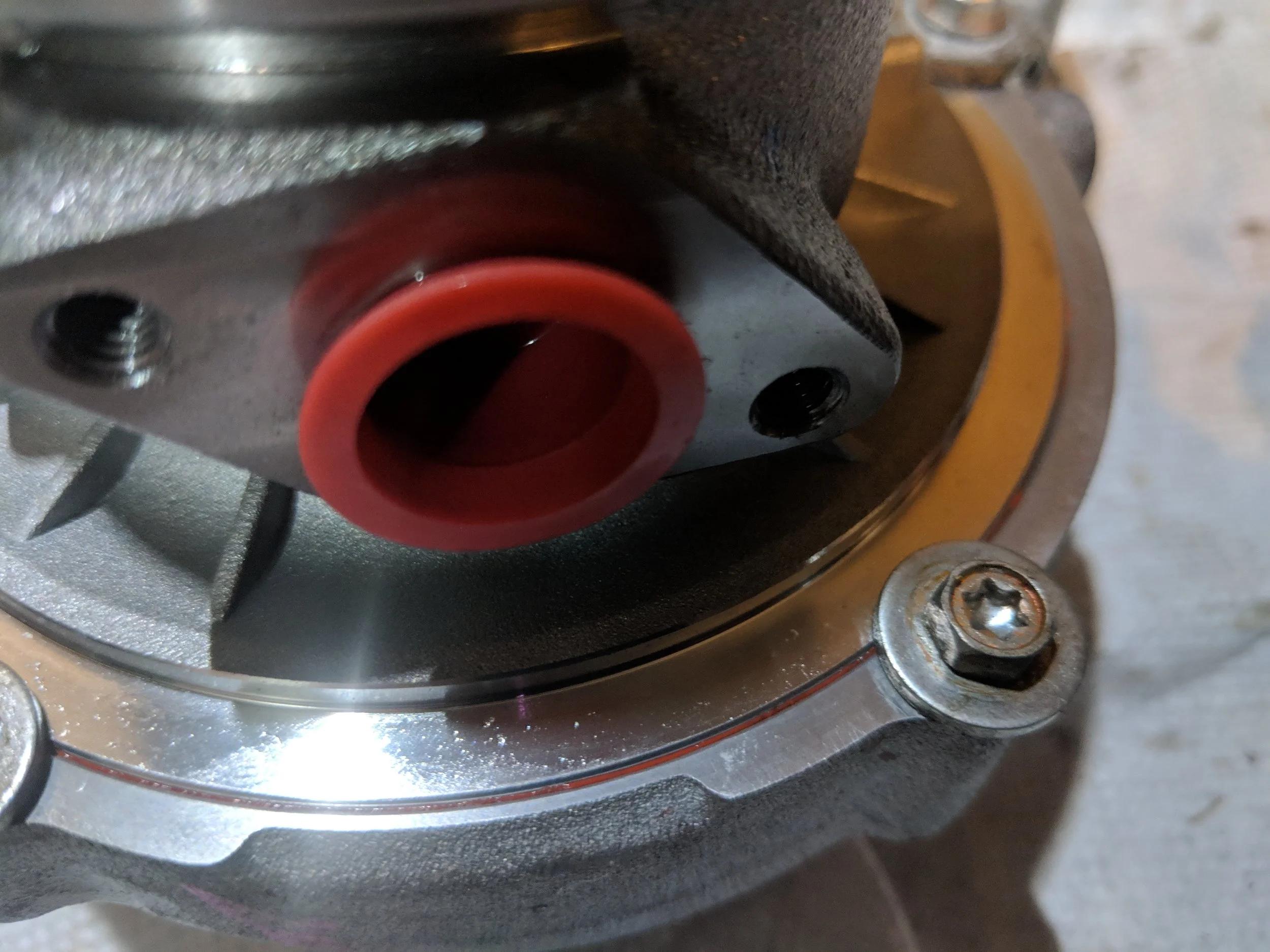
Pictures of rtv bead missing. But it should just start to come out (as seen above) when bolting it together.
Making sure you align it with your prior mark on the cold side and pressing them together firmly. Putting the wastegate back to it’s home and follow that with the other 6 bolts. Tighten them in a star pattern to allow the Rtv to be evenly dispersed and seal up the two pieces. Finishing it off with a final torque sequence. Your Rtv needs around 24 hours to cure but after tightening the bolts you can continue to work on the rest of the turbo.

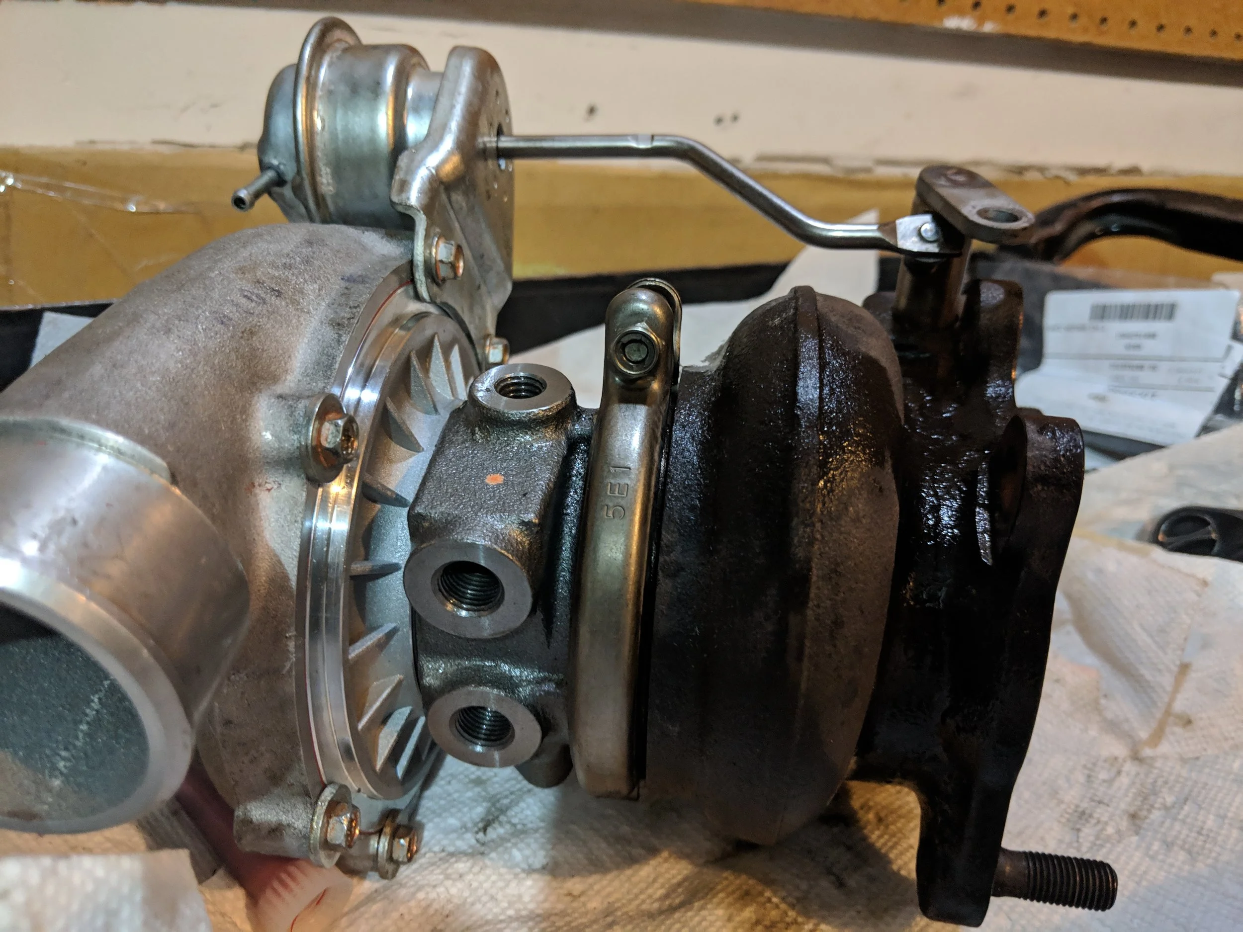
All bolted up with no where to go. Just waiting for the rtv to cure up.
With the turbo sitting on the inlet you can set the hot side on the backside of the CHRA. There is a small alignment pin on the lower side of the hot side that will fit into the CHRA hole. After getting those two pieces together you can put the clamp back over the top. Align your location as to not obstruct you oil feed line or wastegate arm and tighten to spec.

CHRA hole is located on the bottom helps you line up the hotsides dowel pin.

Hotside dowel pin lines everything up.
Now comes the clamp to hold them together and be one step closer to finishing.
With all the parts back together you will take the Wastegate arm and reconnect them. adding the circlip to keep it in place.

Wastegate arm back on. Snap the circlip back in place to keep everything in place.
Lastly you will now put on the coolant hardlines and oil return line. And you have completed your rebuild task! Bask in the beauty that is your rebuilt turbo!

Coolant lines back on and ready to flow.

All ready for action! Quite a few steps but easy enough for everyone!
Ready for being installed and back to boosting. Priming a brand new turbo prior to running it is very important. Burning up the seals or bearings will put you right back into the same position you were in.
Questions, comments, thoughts? Leave them below!
Amazon links:
Subaru turbo oil return gasket
Grimmspeed Uppipe to turbo gasket
Grimmspeed downpipe to turbo gasket